Secondary battery employing safety device

a safety device and secondary battery technology, applied in secondary cell servicing/maintenance, cell components, electrical equipment, etc., can solve the problem of not realizing the discharging operation, and achieve the effect of reducing the effect of heat generation, consuming the energy of the battery cell, and effectively emitted

Active Publication Date: 2007-03-08
LG ENERGY SOLUTION LTD
View PDF8 Cites 83 Cited by
  • Summary
  • Abstract
  • Description
  • Claims
  • Application Information

AI Technical Summary

Benefits of technology

[0023] The resistor serves to consume the energy of the battery cell through the generation of heat when the mechanical connection sensor conducts. Since an excessive amount of electrical energy accumulated in the battery cell must be consumed through the conduction, a large amount of heat may be generated from the resistor. Consequently, heat generated from electric current flowing during the forcible discharge of the battery cell must be effectively emitted, and therefore, the resistor is preferably mounted at a region outside of the battery cell where the effect due to the heat generation is minimized. The region may be the lower end of the battery cell. According to circumstances, the resistor may be mounted at a region spaced apart from the battery cell.
[0024] According to the present invention, the resistance value of the resistor may be adjusted to control the degree of forcible discharge. The resistance value of the resistor may be decided within a range in which the resistance value is greater than the sum of the resistances of a wire and the connection sensor used to connect the resistor, and, at the same time, is not excessive. When the resistance value is too small, flames may occur due to excessively rapid discharge, or extreme heat generation causing fire may occur. When the resistance value is too large, on the other hand, the discharge speed is decreased, and therefore, the safety is deteriorated.

Problems solved by technology

In addition, the discharging operation is not realized through a circuit.

Method used


Image

  • Secondary battery employing safety device
  • Secondary battery employing safety device
  • Secondary battery employing safety device

Examples


Embodiment Construction

[0041] Now, preferred embodiments of the present invention will be described in detail with reference to the accompanying drawings. It should be noted, however, that the scope of the present invention is not limited by the illustrated embodiments.

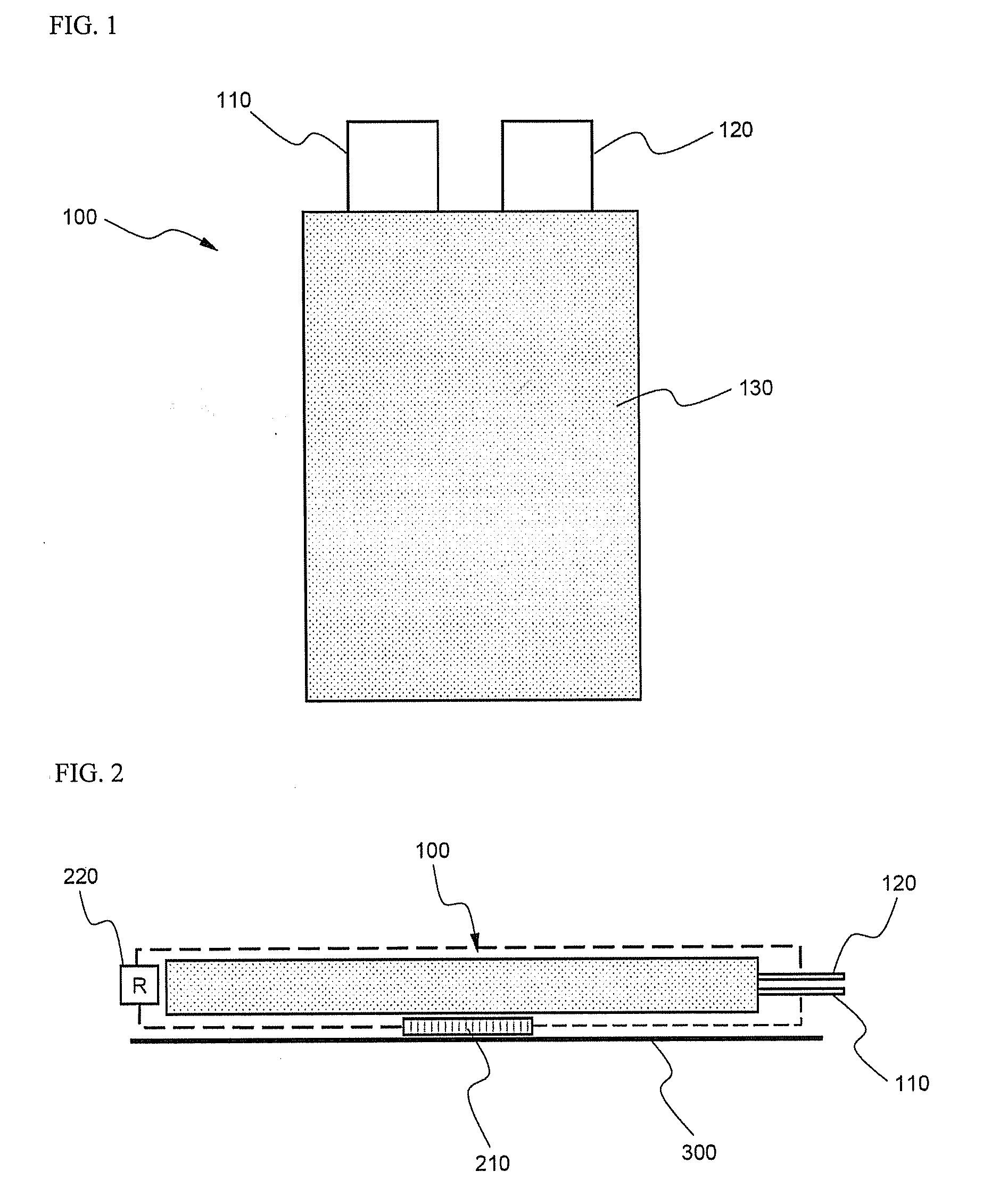
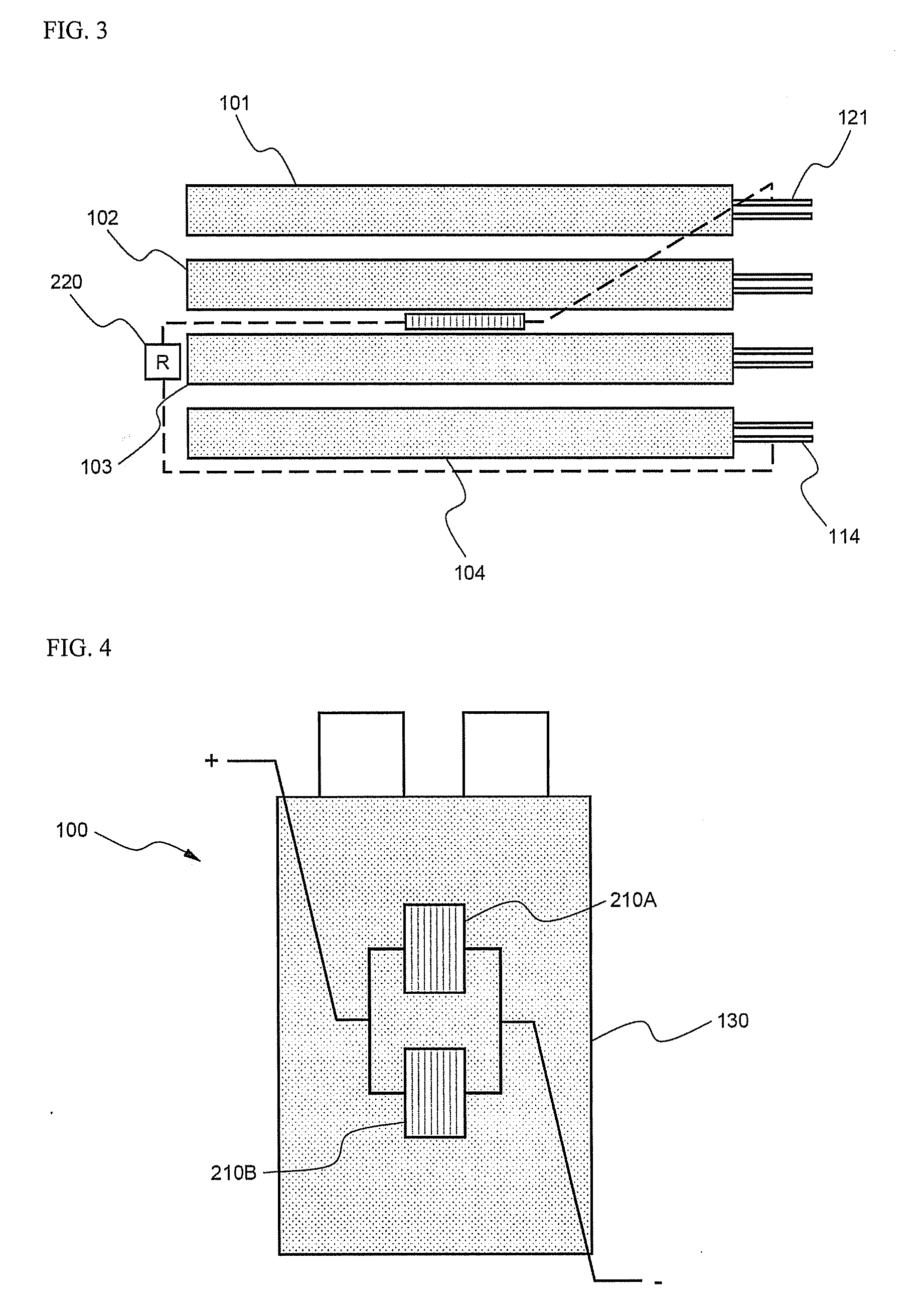
[0042]FIG. 1 is a typical view illustrating the external appearance of a pouch-shaped battery cell 100 according to a preferred embodiment of the present invention. Referring to FIG. 1, the battery cell 100 is constructed in a structure in which an electrode assembly (not shown) is mounted in a pouch-shaped battery case 130, and a cathode tap 110 and an anode tap 120 protrude from the upper end of the battery case 130. The pouch-shaped battery case 130 is constructed in a laminate sheet structure including a metal layer and a resin layer and having an insulative outer surface. Consequently, when the inner pressure of the battery cell 100 is increased, the battery cell 100 easily swells.

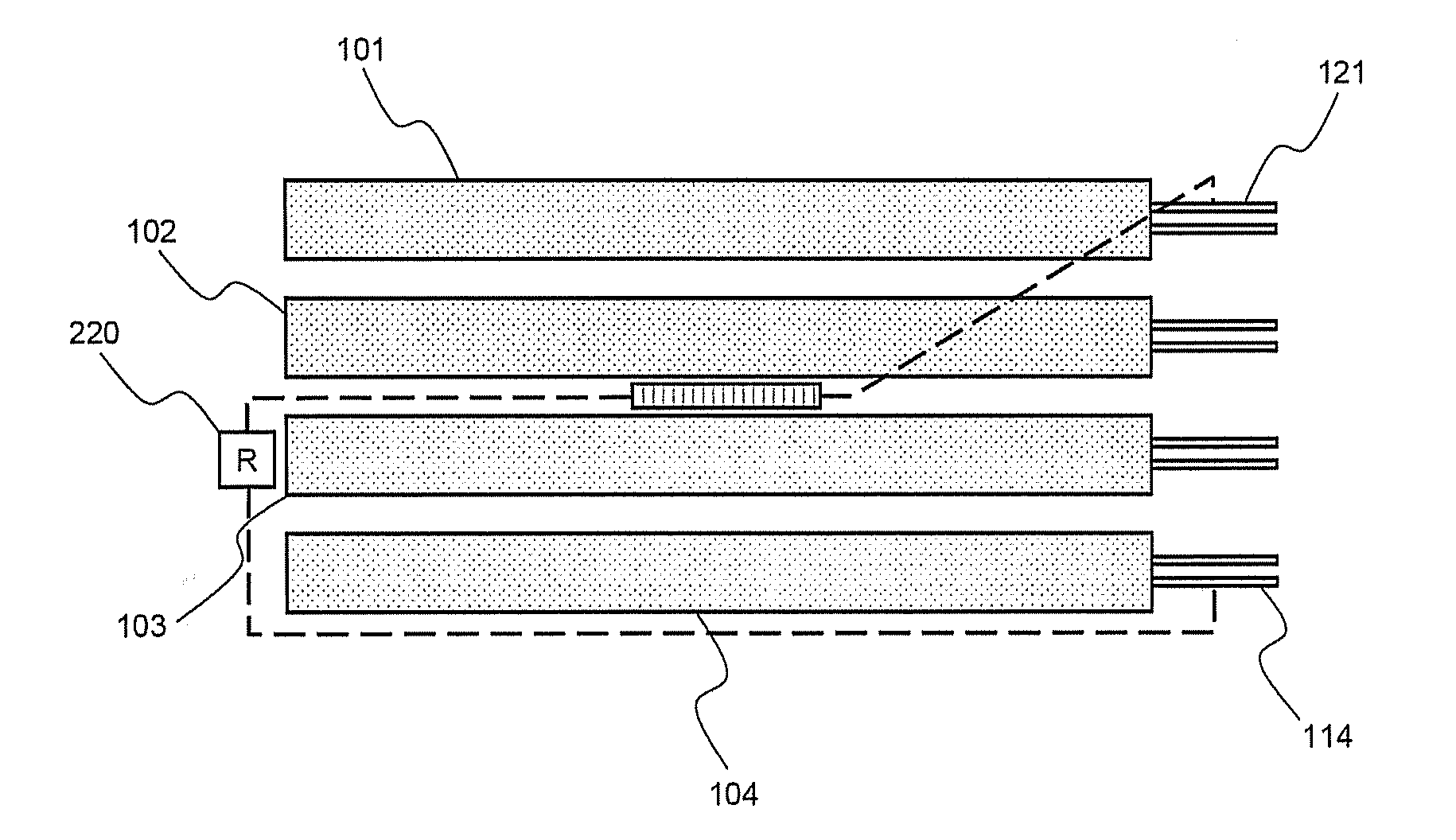
[0043]FIGS. 2 and 3 are sectional views illustrating ...


PUM

PropertyMeasurementUnit
resistancesaaaaaaaaaa
currentaaaaaaaaaa
currentaaaaaaaaaa

Abstract

Disclosed herein is a secondary battery having a mechanical connection sensor, as a safety device, fixed to the outer surface of a prismatic or pouch-shaped battery cell while the mechanical connection sensor is set to OFF. The mechanical connection sensor is connected in series with a resistor having a predetermined resistance value and with a cathode and an anode of the battery cell. When the battery cell swells to a critical value or more due to the abnormal operation of the battery cell, the mechanical connection sensor is turned ON, and therefore, the mechanical connection sensor conducts with the result that the electrical energy of the battery cell is consumed at the resistor. In the secondary battery having the safety device according to the present invention, when the battery swells due to the abnormal response of the battery, energy accumulated in the battery is forcibly consumed, unlike a conventional battery that merely intercepts the current. As a result, the continuous occurrence of the abnormal response is fundamentally prevented, and therefore, more rapid process is possible with excellent pressure sensitivity. Consequently, the safety of the battery is improved.

Description

FIELD OF THE INVENTION [0001] The present invention relates to a secondary battery having a safety device, and, more particularly, to a secondary battery having a mechanical connection sensor, as a safety device, fixed to the outside of a battery cell for detecting the pressure of the battery cell, wherein the mechanical connection sensor is connected with a resistor and terminals of the battery cell, and, when the inner pressure of the battery cell is increased due to the abnormal operation of the battery cell, and therefore, the battery cell swells, the mechanical connection sensor is operated such that electrical energy accumulated in the battery cell is forcibly consumed at the resistor, whereby the energy of the battery cell is decreased, and therefore, the explosion of the battery cell is prevented. BACKGROUND OF THE INVENTION [0002] As the use of portable electronic devices, such as laptop computers, mobile phones, video cameras, digital cameras, etc., has been increased, the...

Claims


Application Information

Patent Timeline
Patent Type & Authority Applications(United States)
IPC IPC(8): H01M10/42H01M2/30
CPCH01M10/42H01M2/34Y02E60/10H01M50/572H01M50/20H01M50/578
Inventor RYU, JI HEONHA, JIN WOONGCHOI, JEONG HEESHIN, YOUNGJOON
Owner LG ENERGY SOLUTION LTD
Why Eureka
Try Eureka