Sheet stacking device

a stacking device and stacking technology, applied in the direction of printing presses, rotary presses, printing presses, etc., can solve the problems of high undesirable deviations in the orientation of sheets relative to one another and relative to the reference plane, insufficient precision in producing accurately formed stacks, and inability to accurately form stacks by known devices. , to achieve the effect of reducing the smearing of any printing pattern produced, improving directional guidance, and reducing slide resistan

Inactive Publication Date: 2007-03-15
OCE TECH
View PDF17 Cites 6 Cited by
  • Summary
  • Abstract
  • Description
  • Claims
  • Application Information

AI Technical Summary

Benefits of technology

[0017] In one embodiment, the rotatably arranged element comprises a freely rotatable guide wheel at the entry point to the slot, positioned and dimensioned such that it extends beyond the circumferential edge of the rotatably arranged element, though it remains within the outer demarcation of the slot. A wheel of this kind will allow an incoming sheet with a lower slide resistance to be accepted into the slot and will improve directional guidance, thus reducing smearing of any printing pattern produced. The improved directional guidance produced by a freely rotatable guide wheel will decrease the risk of a sheet being accepted into the slot in a misaligned manner.
[0018] The present invention also relates to a sheet edge retention hook, where an initial side comprises attachment mechanisms such that the hook may be attached to a frame at least over a part of one revolution while rotating freely and a second side is shaped such that in essence, a horizontally disposed incoming sheet may be easily accepted under the retention hook. This is convenient, as it reduces curling at the edge of the accepted sheet,

Problems solved by technology

A disadvantage of this known device is that, in use, it is not sufficiently precise in producing accurately formed stacks.
In use, it regularly happens that sheets stacked by the known device fail to end up in an orderly manner on the stack form

Method used


Image

  • Sheet stacking device
  • Sheet stacking device
  • Sheet stacking device

Examples


Embodiment Construction

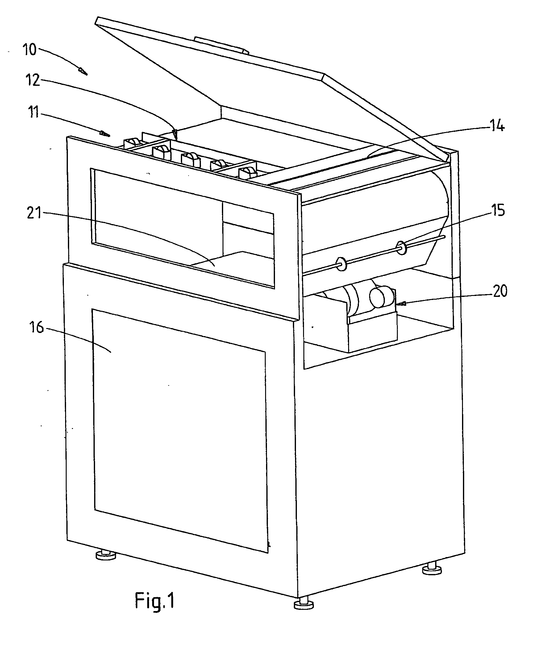
[0030]FIG. 1 is a diagram showing a stacking apparatus 10 in which a device according to the present invention has been mounted. A stacking apparatus 10 of this kind may, for example, be mounted behind a printer. By coupling a printer's sheet outlet to the entry point of the stacking device, sheets from the printer may stacked neatly when the registration actions are performed by the stacking apparatus. A stacking apparatus 10 of this kind may be embodied with various output facilities, such as, but not limited to, a pallet output facility for easily feeding stacks from the stacking device onto a pallet, and a binding facility for binding the stacks together, for example using a plastic strip or another method, in order to maintain the shape of the stack during transport.

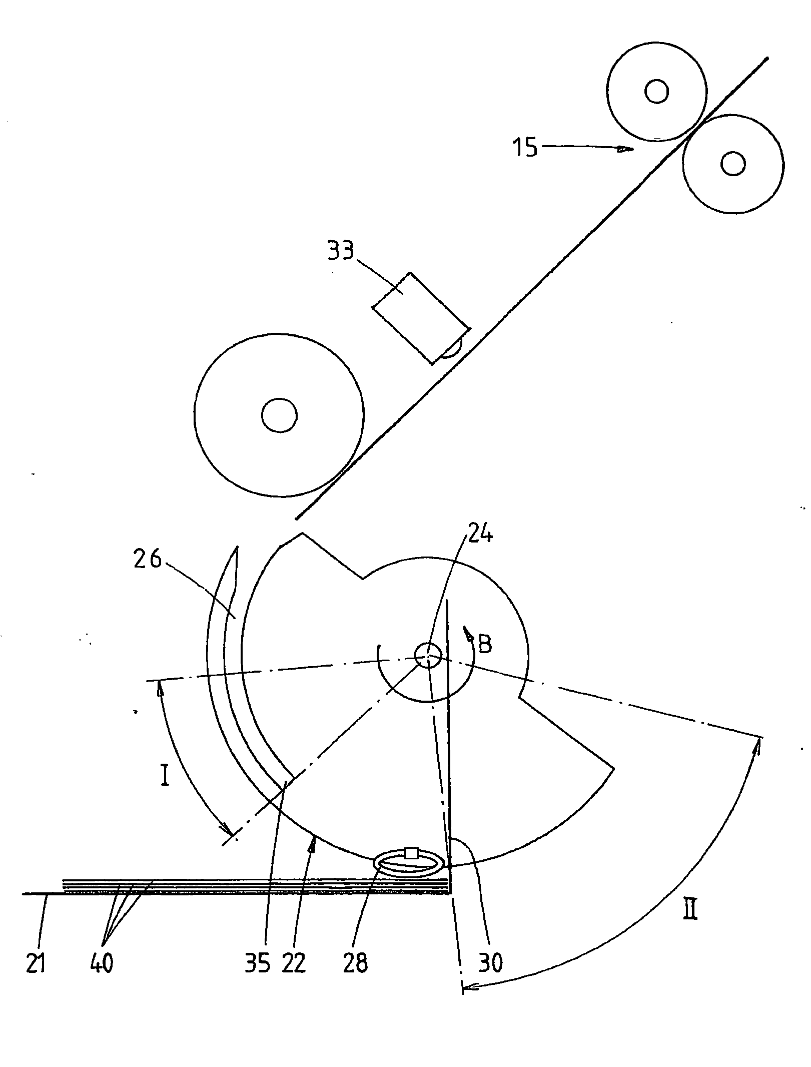
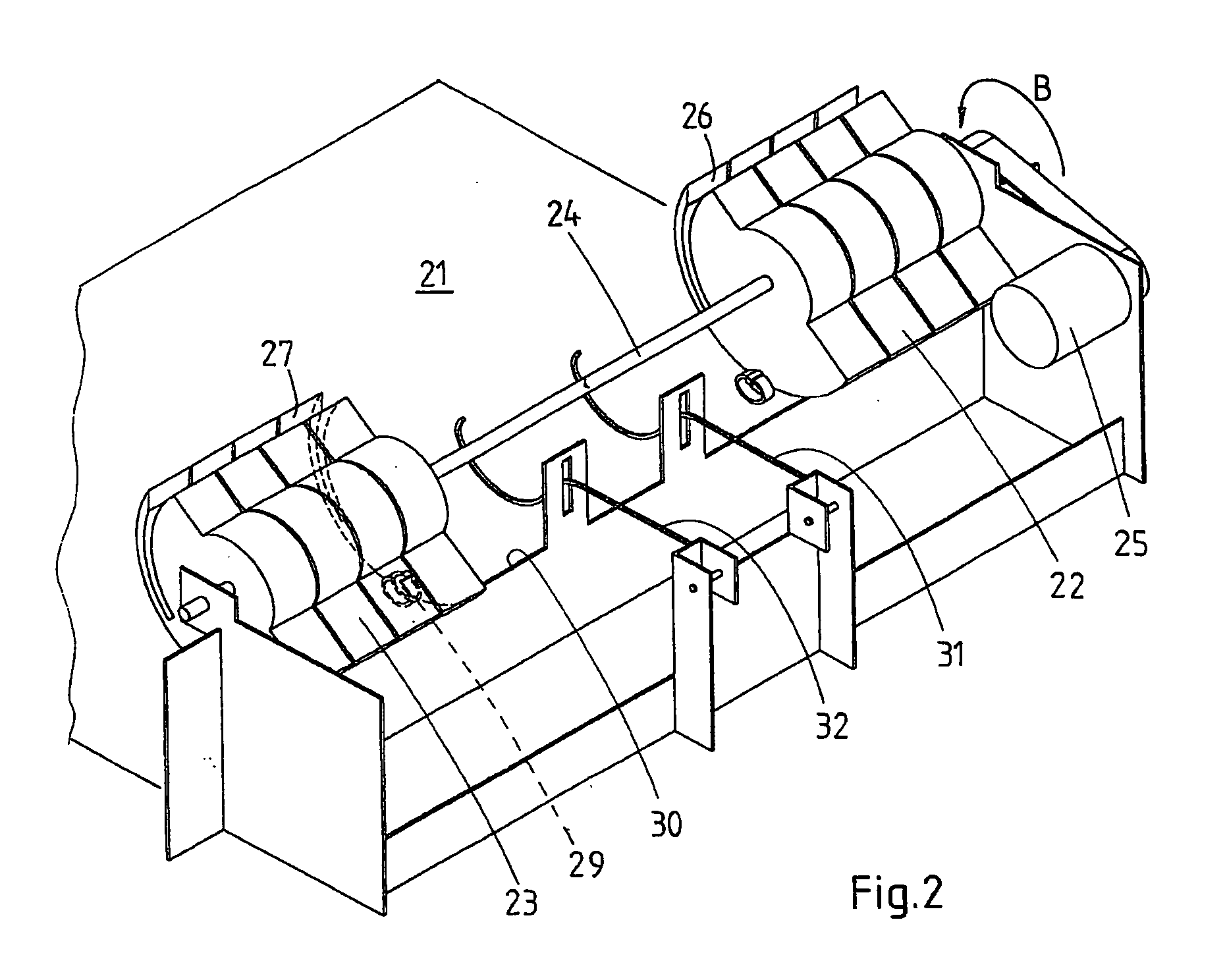
[0031] The stacking unit 10, as shown in FIG. 1, receives sheets via sheet inlet 11. A sheet which has been fed in is then conveyed against a registration wall 13 by means of a registration ruler 12. A top view of ...


PUM


Abstract

A stacking device for incoming sheets, including a receiving plane, a rotatably arranged element, containing a slot at its circumferential edge for accepting at least a portion of a sheet to be stacked, where, in a first rotation zone, the rotatably arranged element accepts the sheet to be stacked and, in a second rotation zone, the accepted sheet is conveyed onto the receiving plane, drive mechanisms for driving the rotatably arranged element, a stop, a closed-loop shaped friction element mounted at the circumferential edge of the rotatably arranged element, which, in operation, transfers a force onto the upper side of the sheet emerging from the slot during at least a part of one revolution of the rotatably arranged element, this force having a component directed towards the stop, wherein the closed-loop shaped friction element is positioned such that, in operation, it does not obstruct the movement of a sheet while the latter is accepted into the slot in the first rotation zone.

Description

[0001] This application claims the priority benefit of Dutch Patent Application No. 1029837 filed Aug. 31, 2005 and Dutch Patent Application No. 2000015 filed on Feb. 23, 2006, which are hereby incorporated by reference. BACKGROUND OF THE INVENTION [0002] The present invention relates to a stacking device for incoming sheets, comprising a receiving plane or station, a rotatably arranged element, containing a slot at its circumferential edge for accepting at least a portion of a sheet to be stacked, where, in a first rotation zone, the rotatably arranged element may accept the sheet to be stacked and, in a second rotation zone, the accepted sheet is conveyed onto the receiving station, drive mechanisms for driving the rotatably arranged element, a stop, a friction element e.g., a closed-loop shaped friction element mounted at the circumferential edge of the rotatably arranged element, which, in operation, during at least part of one revolution of the rotatably arranged element, trans...

Claims


Application Information

Patent Timeline
IPC IPC(8): B41F13/24
CPCB65H29/40B65H31/36B65H2801/06B65H2404/651B65H2404/265
Inventor DINNISSEN, JOHANNES H.A.
Owner OCE TECH
Why Eureka
Try Eureka