Power generating system

Inactive Publication Date: 2007-03-15
KK TOSHIBA
View PDF4 Cites 10 Cited by
  • Summary
  • Abstract
  • Description
  • Claims
  • Application Information

AI Technical Summary

Benefits of technology

[0009] Since the coreless coil is employed as the stator coil of the power generator, the power generating system can reduce the core loss as compared with the conventional equipment. However, the magnetic circuit would not be closed without an iron core. As a result, the density of flux interlinking the stator coils (coreless coil) could not be increased such that the power generation efficiency would be reduced. In view of the problem, the back yoke is disposed at the side of the stator coils which is opposed to another side thereof further confronting the

Problems solved by technology

As a result, the density of flux interlinking the stator coils (coreless coil) c

Method used


Image

  • Power generating system
  • Power generating system
  • Power generating system

Examples


Embodiment Construction

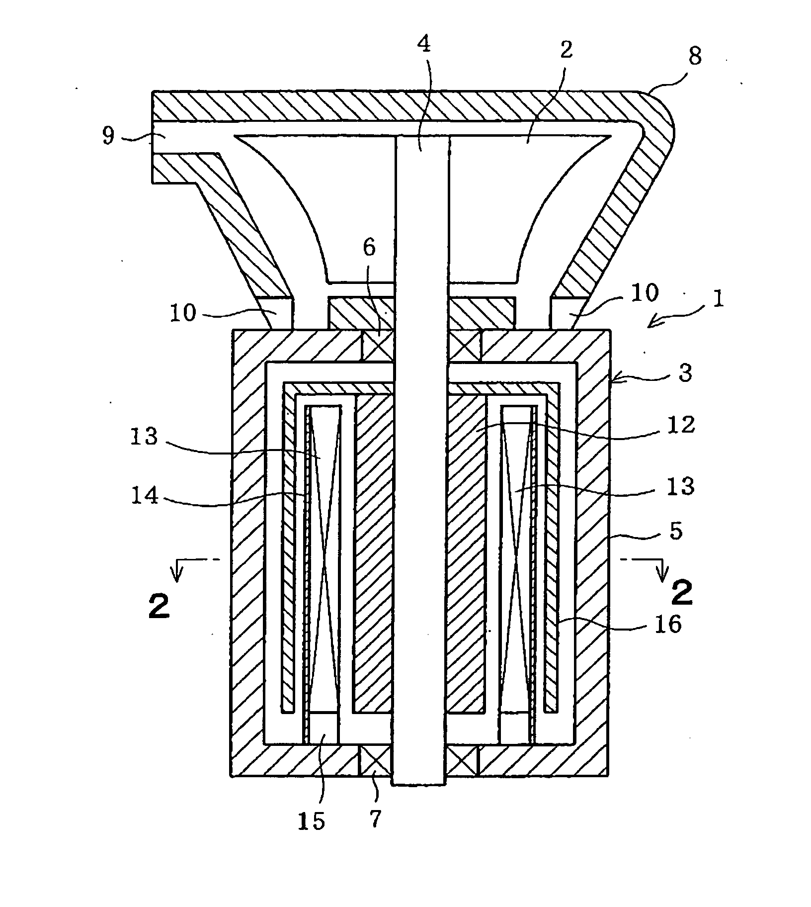
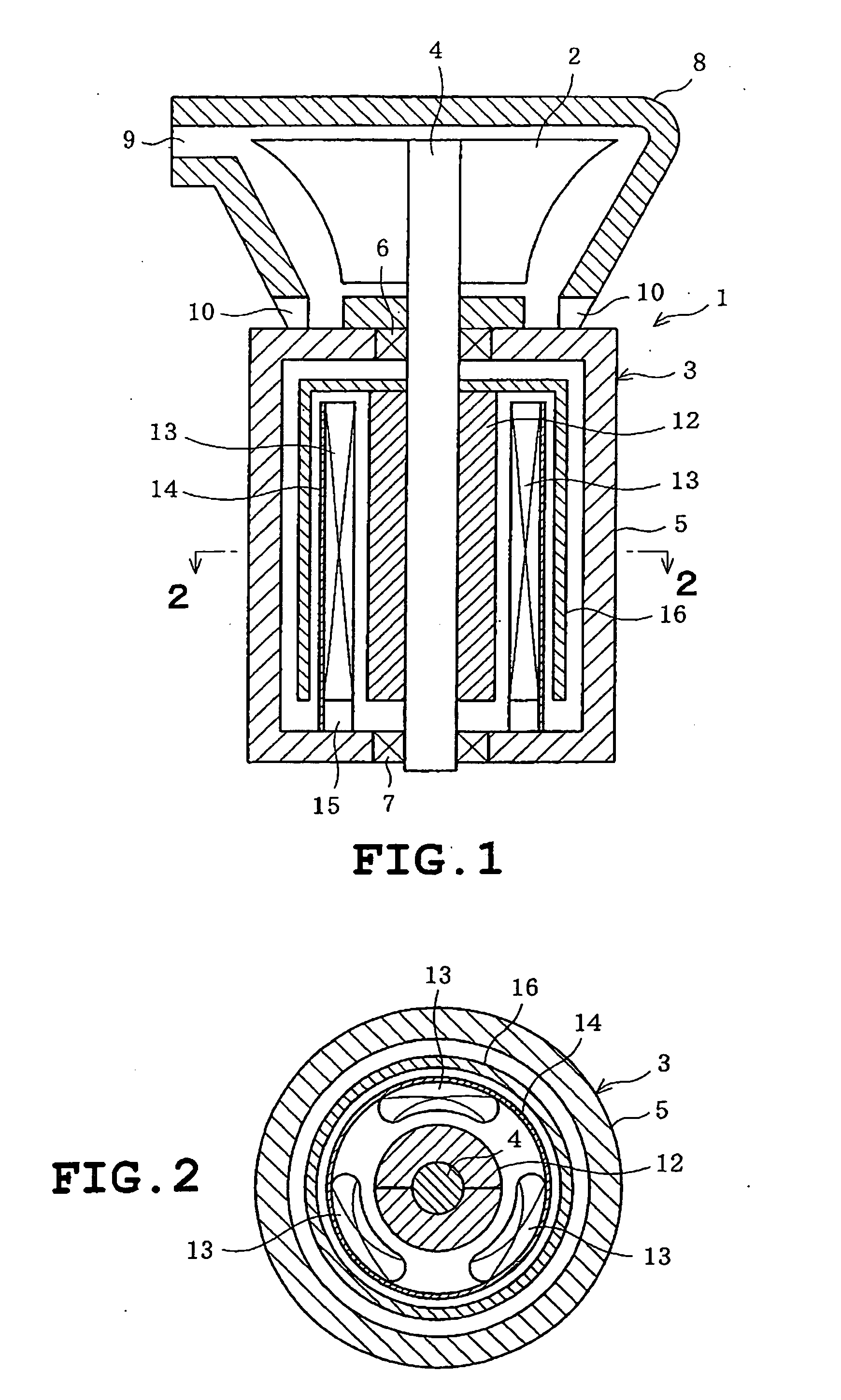
[0016] A first embodiment of the present invention will be described with reference to FIGS. 1 to 4. Referring to FIG. 1, a power generating system 1 of the invention includes an upper turbine 2 and a lower power generator 3. The turbine 2 and the power generator 3 are unitized. The turbine 2 is mounted on one end of a rotating shaft 4 so as to be rotatable therewith. The power generator 3 includes a substantially cylindrical outer casing 5 having upper and lower ends on both of which the rotating shaft 4 is rotatably supported via respective bearings 6 and 7. The turbine 2 is covered with a turbine casing 8 formed with an inlet 9 and an outlet 10. The inlet 9 is located at an upper outer periphery of the turbine casing 8 so as to correspond to an outer periphery of the turbine 2. The outlet 10 is located near to the outer casing 5 of the power generator 3.

[0017] A cylindrical permanent-magnet rotor 12 is mounted on the rotating shaft 4 so as to be located within the outer casing 5...


PUM


Abstract

A small power generating system includes a turbine driven by a fluid, a power generator including a permanent magnet rotor having a permanent magnet and rotated together with the turbine and a plurality of stator coils each of which is comprised of a coreless coil, the rotor being rotated such that voltage is induced on the stator coils, whereby power is generated by the power generator, and a back yoke disposed at one of two opposed sides of the stator coils which is opposed to the other side thereof further confronting the permanent magnet of the rotor, the back yoke being made of a magnetic material with a predetermined electrical resistance.

Description

CROSS-REFERENCE TO RELATED APPLICATIONS [0001] This application is based upon and claims the benefit of priority from the prior Japanese Patent Application No. 2005-262131, filed on Sep. 9, 2005, the entire contents of which are incorporated herein by reference. BACKGROUND OF THE INVENTION [0002]1. Field of the Invention [0003] The present invention relates to power generating systems and more particularly to a small power generating system including a turbine and a power generator. [0004] 2. Description of the Related Art [0005] JP-A-2003-286862 discloses a micro-turbine power generating system in which with high-speed rotation of turbine by a gas (fluid), a permanent magnet type rotor of a power generator is rotated at high speeds together with the turbine. Rotation of the rotor induces voltage on a stator coil of the power generator so that electrical power is generated. [0006] A stator of the power generator includes an iron core and a stator coil wound on the iron core in the f...

Claims


Application Information

Patent Timeline
IPC IPC(8): H02K21/12H02K1/00H02K1/12
CPCH02K7/1823H02K21/24H02K21/222
Inventor ITO, TETSUYAOKADA, KYOUICHIUCHIDA, TATSURO
Owner KK TOSHIBA
Why Eureka
Try Eureka