Stator punching sheet of high-voltage permanent-magnet synchronous motor, winding stator and motor

A technology of stator punching and permanent magnet synchronization, which is applied in synchronous machines, synchronous machine parts, and electric components, etc., can solve the problem of uneven distribution of the air gap magnetic field of the motor, large cogging torque and core loss, and affect the running performance of the motor. and other problems, to achieve the effect of improving the air gap magnetic field distribution, reducing the core loss, and increasing the difficulty of embedding

Inactive Publication Date: 2019-04-16
NANTONG UNIVERSITY
View PDF5 Cites 3 Cited by
  • Summary
  • Abstract
  • Description
  • Claims
  • Application Information

AI Technical Summary

Problems solved by technology

[0003] Under normal circumstances, there is no magnetic groove wedge groove on the stator punching plate of the high-voltage permanent magnet motor, and the integer winding groove is used at the same time with a wide groove, which results in uneven distribution of the air gap magnetic field of the motor, and relatively high cogging torque and core loss. Large, the temperature rise of the motor is high during rated operation, which seriously affects the operation performance of the motor
[0004] Based on the above reasons, it is necessary to improve the current high-voltage permanent magnet synchronous motor due to the uneven distribution of the air gap magnetic field, large cogging torque and large core loss, etc., resulting in large motor noise and vibration, and high core loss.

Method used


Image

  • Stator punching sheet of high-voltage permanent-magnet synchronous motor, winding stator and motor
  • Stator punching sheet of high-voltage permanent-magnet synchronous motor, winding stator and motor
  • Stator punching sheet of high-voltage permanent-magnet synchronous motor, winding stator and motor

Examples


Embodiment Construction

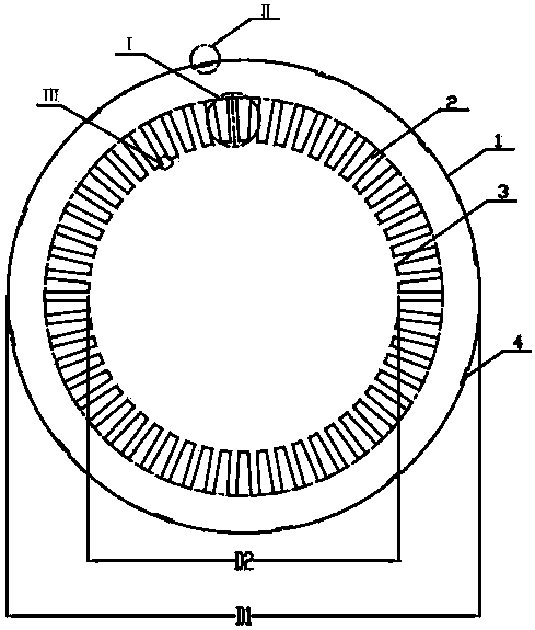
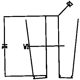
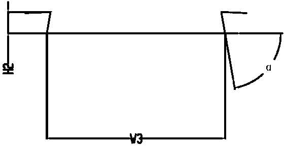
[0019] Referring to the accompanying drawings, a high-voltage permanent magnet synchronous motor stator stamping, including a stamping body 1, is characterized in that: the stator stamping body 1 is circular, the outer diameter D1 is 730 mm, and the inner diameter D2 is 480 mm. There are 54 evenly distributed rectangular winding slots 2 on the inner circle of the stator body 1, the slot width W1 is 13.7 mm, and the slot height H1 is 65 mm; the opening of the winding slot 2 is provided with a magnetic slot for placing magnetic slot wedges Wedge slot 3; Magnetic slot Wedge slot 3 is semicircular, its radius R2 is 1 mm, and the slot opening width W2 is 15.7 mm. The size of the arc radius R3 is 0.2mm; there are 12 uniformly distributed dovetail-shaped positioning slots 4 on the outer circle of the stator punching body 1, the size of the slot height H2 is 3 mm, the size of the slot bottom width W3 is 26 mm, and the slot shoulder is oblique Angle α degrees is 78°.

[0020] The pate...


PUM


Abstract

The invention discloses a stator punching sheet of a high-voltage permanent-magnet synchronous motor, a winding stator and the motor. A stator punching sheet body is in a round shape, 54 rectangular winding grooves are formed in the stator body and are uniformly distributed along a circumference, the widths W1 of the winding grooves are 13.7 millimeters, H1 of the winding grooves are 65 millimeters, a magnetic groove wedge slot is formed in a winding groove opening and is used for placing a magnetic groove wedge, 12 swallowtail positioning grooves are formed in an outer circle profile of the stator punching sheet body and are uniformly distributed along the circumference, the magnetic groove wedge slot is in a semi-circular shape, the radius R2 of the magnetic groove wedge slot is 1 millimeter, a fillet is arranged at a connection position of the magnetic groove wedge slot and the winding groove, the arc radius R3 is 0.2 millimeter, and the opening width W2 of the magnetic groove wedgeslot is 15.7 millimeters. The semi-circular magnetic groove wedge is employed, the air gap magnetic field distribution is improved, and the vibration and the noise of the motor are reduced; and an inner circle and an outer circle of the stator punching sheet and the winding groove are reasonable in design, the iron core loss of the motor is reduced, and the running performance of the motor is improved.

Description

technical field [0001] The invention relates to the field of motor manufacturing, and more specifically relates to a high-voltage permanent-magnet synchronous motor stator stamping and winding stator and motor, belonging to the field of motors. Background technique [0002] The electric motor is a tool for energy conversion, which is mainly composed of a stator and a rotor. The stator is mainly composed of a winding coil and a stator core, and the stator core is formed by laminating many stator punches. The stator punch is an important part of the motor, and its inner and outer diameter, winding slot size and number will have a direct impact on the performance of the motor. [0003] Under normal circumstances, there is no magnetic groove wedge groove on the stator punching plate of the high-voltage permanent magnet motor, and the integer winding groove is used at the same time with a wide groove, which results in uneven distribution of the air gap magnetic field of the moto...

Claims


Application Information

Patent Timeline
Patent Type & Authority Applications(China)
IPC IPC(8): H02K1/16H02K3/493H02K21/02
CPCH02K1/165H02K3/493H02K21/025H02K2201/03H02K2213/03
Inventor 顾海勤杨奕张桂红顾雪政杨慧黄媛媛焦子韵梅天祥任晓琳
Owner NANTONG UNIVERSITY
Why Eureka
Try Eureka