Variable-magnification optical system and image taking apparatus

a technology of applied in the field of variable magnification optical system and image taking apparatus, can solve the problems of not offering satisfactorily high performance, and achieve the effects of reducing (correcting) various aberrations, reducing the disadvantages resulting, and aggravating aberrations and movement strokes of lens groups

Inactive Publication Date: 2007-03-15
KONICA MINOLTA PHOTO IMAGING
View PDF7 Cites 11 Cited by
  • Summary
  • Abstract
  • Description
  • Claims
  • Application Information

AI Technical Summary

Benefits of technology

[0010] In view of the conventionally encountered inconvenience mentioned above, it is an object of the present invention to provide a compact high-performance variable-magnification optical system, and to provide an image-taking apparatus incorporating such a variable-magnification optical system.
[0013] In the variable-magnification optical system constructed as described above, for reasons related to its optical power arrangement, the optical aperture stop is typically disposed near the third lens group. Then, the optical axis changing element that changes (for example, bends) the optical axis of the light beam of which part has been intercepted is disposed to the image side of the optical aperture stop. As a result, as compared with a variable-magnification optical system that extends in one direction (that is, a straight optical system), the variable-magnification optical system according to the present invention is more compact in that direction by the length of the lens groups disposed on the downstream side of where the optical axis is bent.
[0014] When the thus shortened variable-magnification optical system is incorporated in an image-taking apparatus, the lens groups disposed to the image side of the optical axis changing element can easily be built in the chassis (body) of the image-taking apparatus. Thus, as compared with an image-taking apparatus incorporating a straight optical system, the image-taking apparatus according to the present invention is more compact, for example, in the depth direction.
[0015] Since the beam size is smaller on the image side than on the object side, the optical axis changing element that changes the optical axis when the beam size is small can be comparatively compact. Thus, simply through the inclusion of the comparatively compact optical axis changing element, the variable-magnification optical system according to the present invention permits part of its lens groups to be properly built in the limited space inside the housing of an image-taking apparatus.
[0018] Conditional formula (1) defines a preferable range of the magnification variation ratio of the third lens group. Within that range, the responsibility for magnification variation can be properly distributed between, for example the second and third lens groups. Hence, within the range defined by conditional formula (1), no lens group is excessively responsible for magnification variation. Thus, it is possible to alleviate the disadvantages resulting from excessive responsibility for magnification variation, namely the aggravation of aberrations and the increase of the movement strokes of the lens groups. Thus, according to the present invention, it is possible to realize a compact variable-magnification optical system while reducing (correcting) various aberrations.
[0019] As described above, according to the present invention, the magnification variation ratio of the third lens group can be set in a proper range. Thus, the responsibility for magnification variation can be properly distributed between, for example the second and third lens groups. Thus, it is possible to realize a compact variable-magnification optical system while reducing (correcting) the various aberrations provided by the individual lens groups. Moreover, by incorporating such a variable-magnification optical system in an image-taking apparatus, it is possible to realize a compact high-performance image-taking apparatus.

Problems solved by technology

These, however, are designed to offer zoom ratios of 7× to 10×, and therefore do not offer satisfactorily high performance.

Method used


Image

  • Variable-magnification optical system and image taking apparatus
  • Variable-magnification optical system and image taking apparatus
  • Variable-magnification optical system and image taking apparatus

Examples


first embodiment

[0047] An embodiment of the present invention will be described below with reference to the drawings.

[0048] 1. Digital Still Camera

[0049]FIG. 7 is a block diagram showing the internal configuration of a digital still camera (DSC) 29 as an example of an image-taking apparatus according to the present invention.

[0050] As shown in FIG. 7, the DSC 29 includes a variable-magnification optical system OS, a flash FL, an optical system driving section 13, an image sensor SR, a signal processing section 14, a display section 15, a recording section 16, a recording medium 17, an operation section 18, and a control section 19.

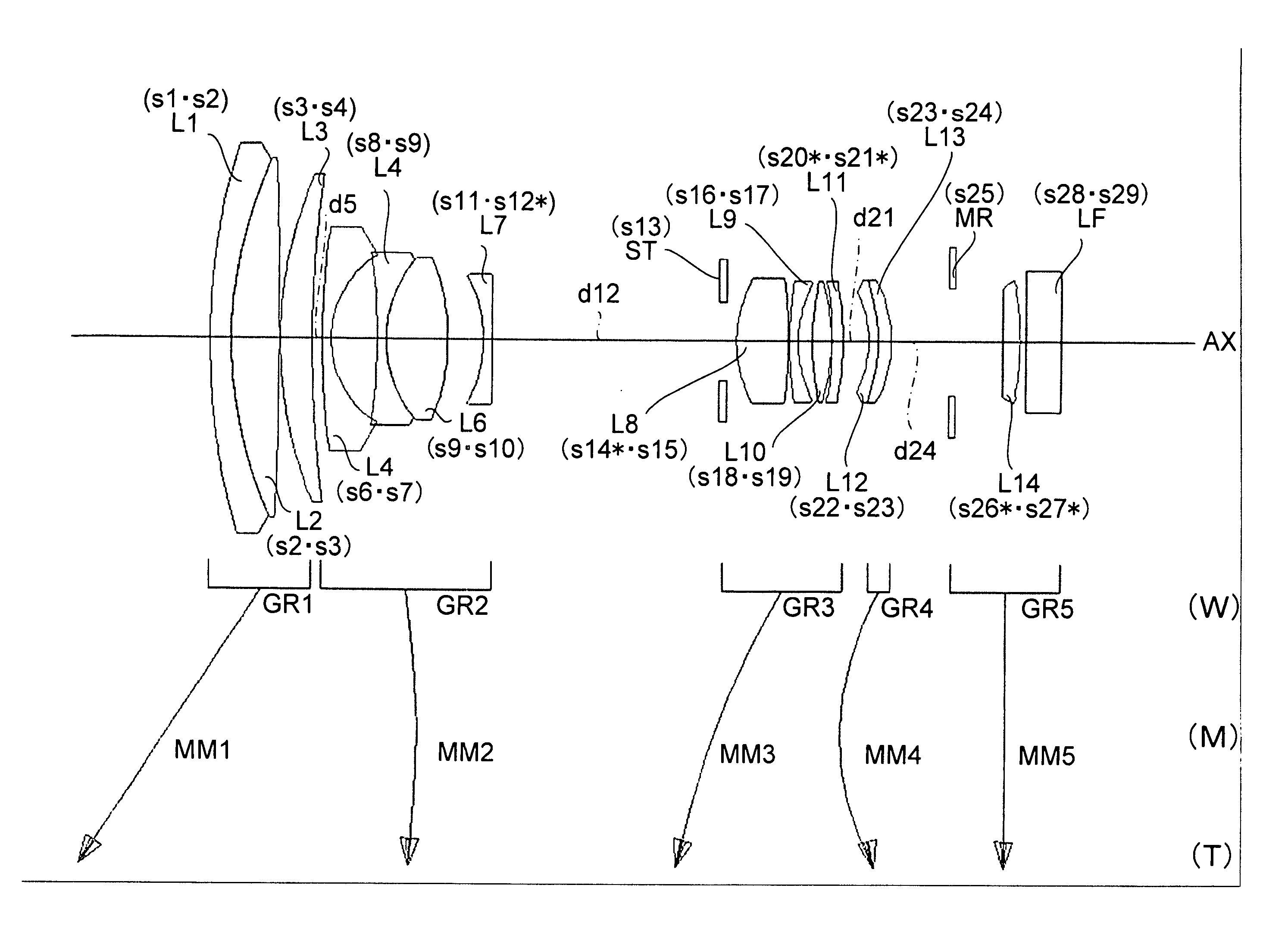
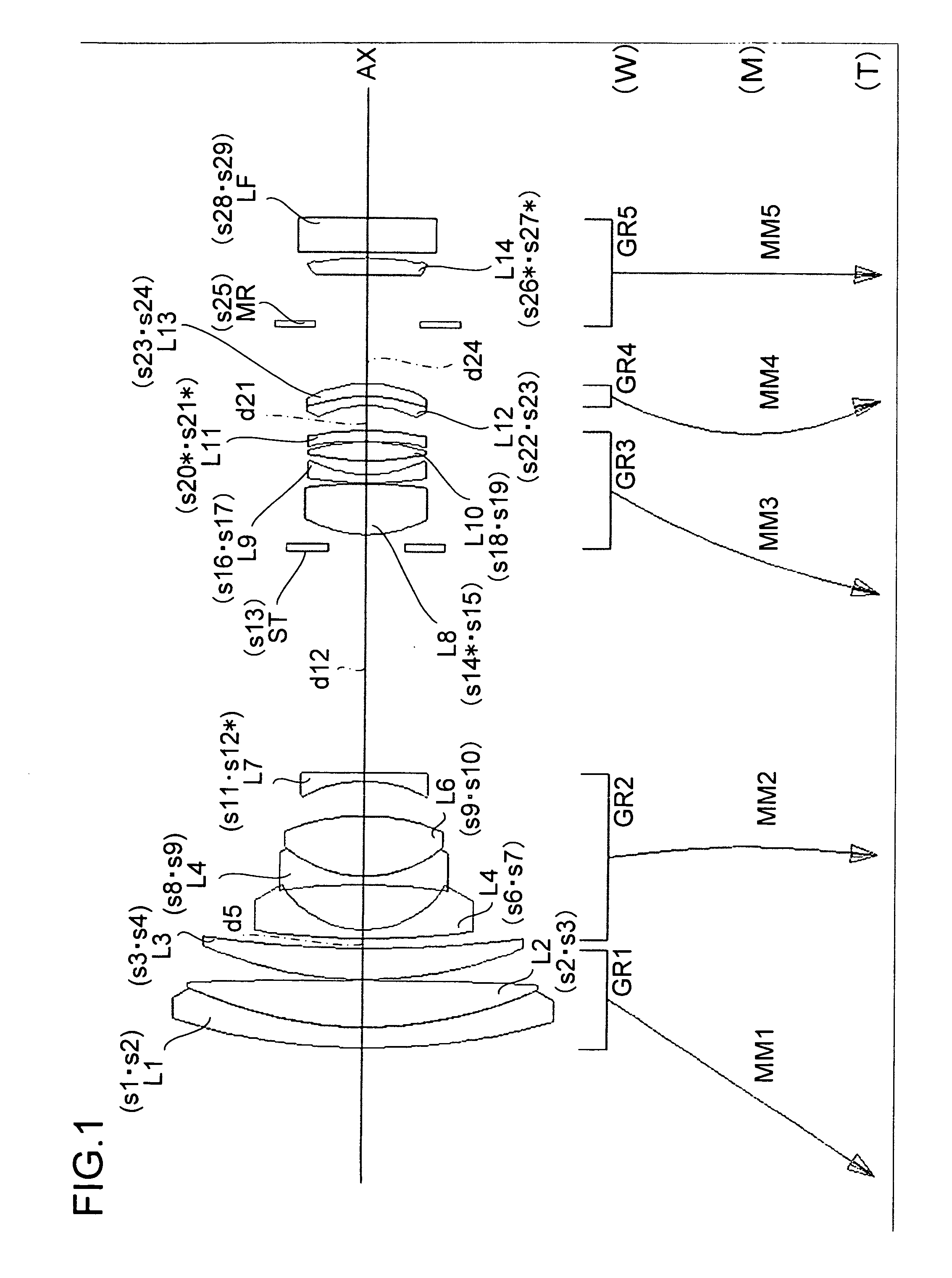
[0051] The variable-magnification optical system OS directs the light from the shooting target (subject, object) to the image sensor SR, and meanwhile images the light on the photosensitive surface (image surface) of the image sensor SR. Thus, the variable-magnification optical system OS may also be called an imaging optical system or an image-taking optical system. T...

second embodiment

[0186] Another embodiment of the present invention will be described below with reference to the drawings. Such members as serve the same purposes as their counterparts in the first embodiment are identified with common reference numerals and symbols, and no explanations thereof will be repeated.

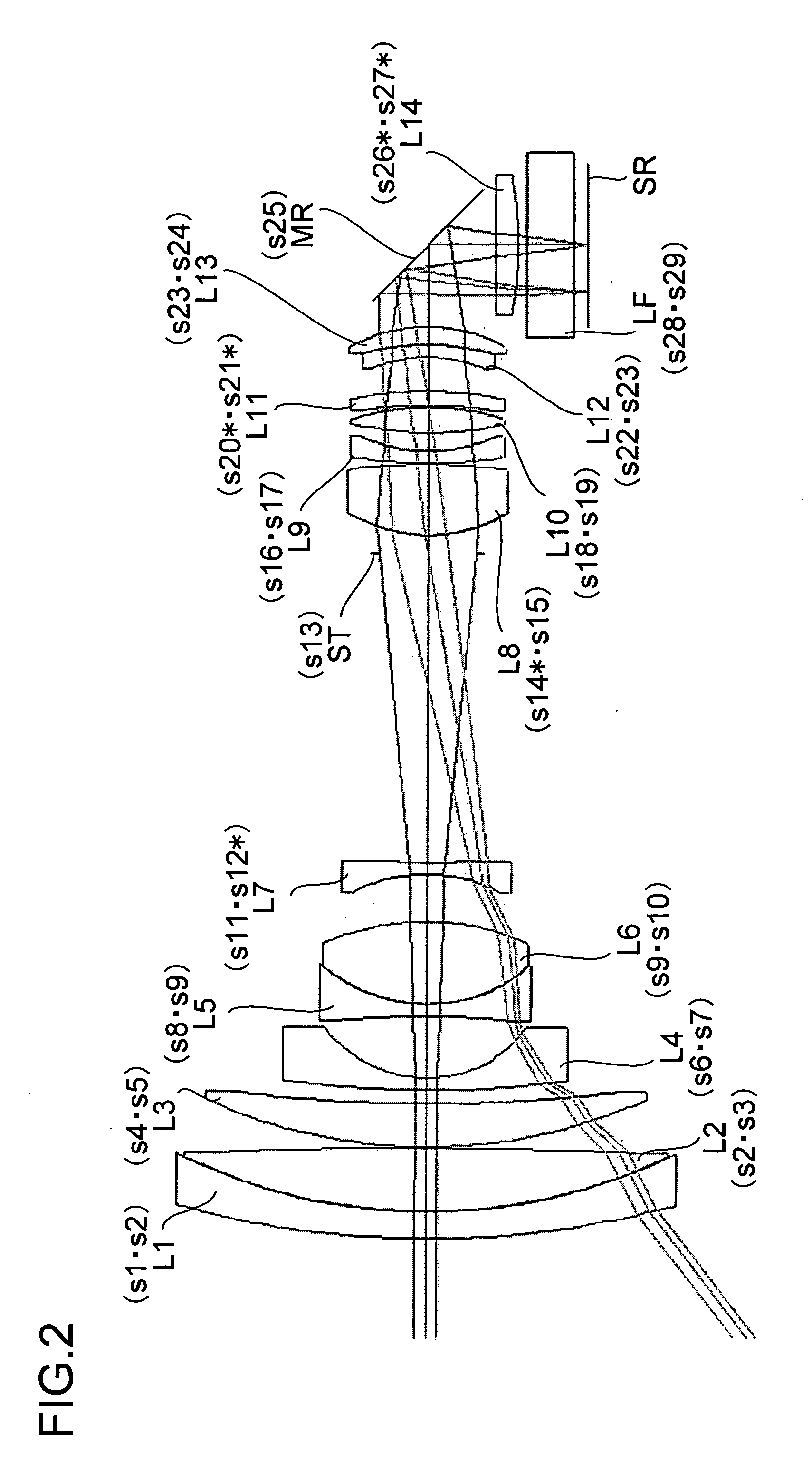
[0187] In the variable-magnification optical system OS (Example 1) of the first embodiment, the reflective mirror MR is disposed to the image side of the fourth lens group GR4. This, however, is not meant to limit the position of the reflective mirror MR in any way. To substantiate that, another (Example 2) example of the variable-magnification optical system OS will now be described with reference to FIGS. 8 and 9. In FIGS. 8 and 9, the same conventions as those used in FIGS. 1 and 2 are used.

1. Variable-Magnification Optical System of Example 2

[0188] The variable-magnification optical system OS of Example 2 shown in FIGS. 8 and 9 includes, from the shooting target (object) side, a firs...


PUM


Abstract

A variable-magnification optical system has a plurality of lens groups that image a light beam from the object side on an image sensor, an optical aperture stop that intercepts part of the light beam heading for the image sensor, and a reflective mirror that changes the optical axis of the light beam of which part has been intercepted by the optical aperture stop. The plurality of lens groups include at least lens groups arranged in a positive-negative-positive-positive optical power arrangement, and at least two of the lens groups are moved for zooming from the wide-angle end to the telephoto end. The variable-magnification optical system fulfills a prescribed conditional formula.

Description

[0001] This application is based on Japanese Patent Application No. 2005-267874 filed on Sep. 15, 2005, the contents of which are hereby incorporated by reference. BACKGROUND OF THE INVENTION [0002] 1. Field of the Invention [0003] The present invention relates to a variable-magnification optical system for use in a lens unit or the like, and also relates to an image-taking apparatus incorporating such a variable-magnification optical system. [0004] 2. Description of Related Art [0005] In recent years, as personal computers (PC) become widespread, digital still cameras (image-taking apparatuses), which permit easy capturing of images, have been becoming increasingly popular. In such digital still cameras (DSCs), as in cameras using silver-halide film (silver-halide cameras), compactness (slimness) and high performance (for example, a high magnification variation ratio and high aberration correction performance) are sought. Accordingly, compactness and high performance are sought in ...

Claims


Application Information

Patent Timeline
Patent Type & Authority Applications(United States)
IPC IPC(8): G02B15/14
CPCG02B15/173G02B15/145129
Inventor TERADA, MAMORU
Owner KONICA MINOLTA PHOTO IMAGING
Why Eureka
Try Eureka