Method and apparatus for generating at least one section of a virtual 3D model of a body interior

Active Publication Date: 2007-03-15
LUDWIG MAXIMILIAN UNIV +1
View PDF12 Cites 52 Cited by
  • Summary
  • Abstract
  • Description
  • Claims
  • Application Information

AI Technical Summary

Benefits of technology

[0045] Starting from a reference point at which the endoscope is located at the beginning of the method, the Inertial sensor system is used to acquire all movement, that is to say all changes in position, as well as all changes in orientation of the endoscope by measuring acceleration, and the current position and orientation of the endoscope are determined therefro

Problems solved by technology

However, it can occur that regions of the wall of the bladder are overlooked, that is to say are not endoscopically acquired.
If the nonacquired regions of the wall of the bladder are, if appropriate, malign tissue areas, this can have serious consequences for the patient.
One reason why omissions of tissue areas or surface areas of the bladder come about during the endoscopic examination of the bladder is that the orientation of the doctor in the substantially spherical interior of the bladder is rendered difficult by the restricted field of view of an endoscope.
Moreover, since the endoscopic image visually displayed on a monitor has no spatial depth but, only a “two-dimensional” effect, it is not possible solely with the aid of the acquired endoscopic image to judge the surface area from which this endoscopic image originates.
If, for example, a number of endoscopic images of different surface areas of the body interior are acquired and documented, and if a pathological finding is recorded on one of the endoscopic images, it is no longer possible later on to use the endoscopic images to determine unambiguously from

Method used


Image

  • Method and apparatus for generating at least one section of a virtual 3D model of a body interior
  • Method and apparatus for generating at least one section of a virtual 3D model of a body interior
  • Method and apparatus for generating at least one section of a virtual 3D model of a body interior

Examples


Embodiment Construction

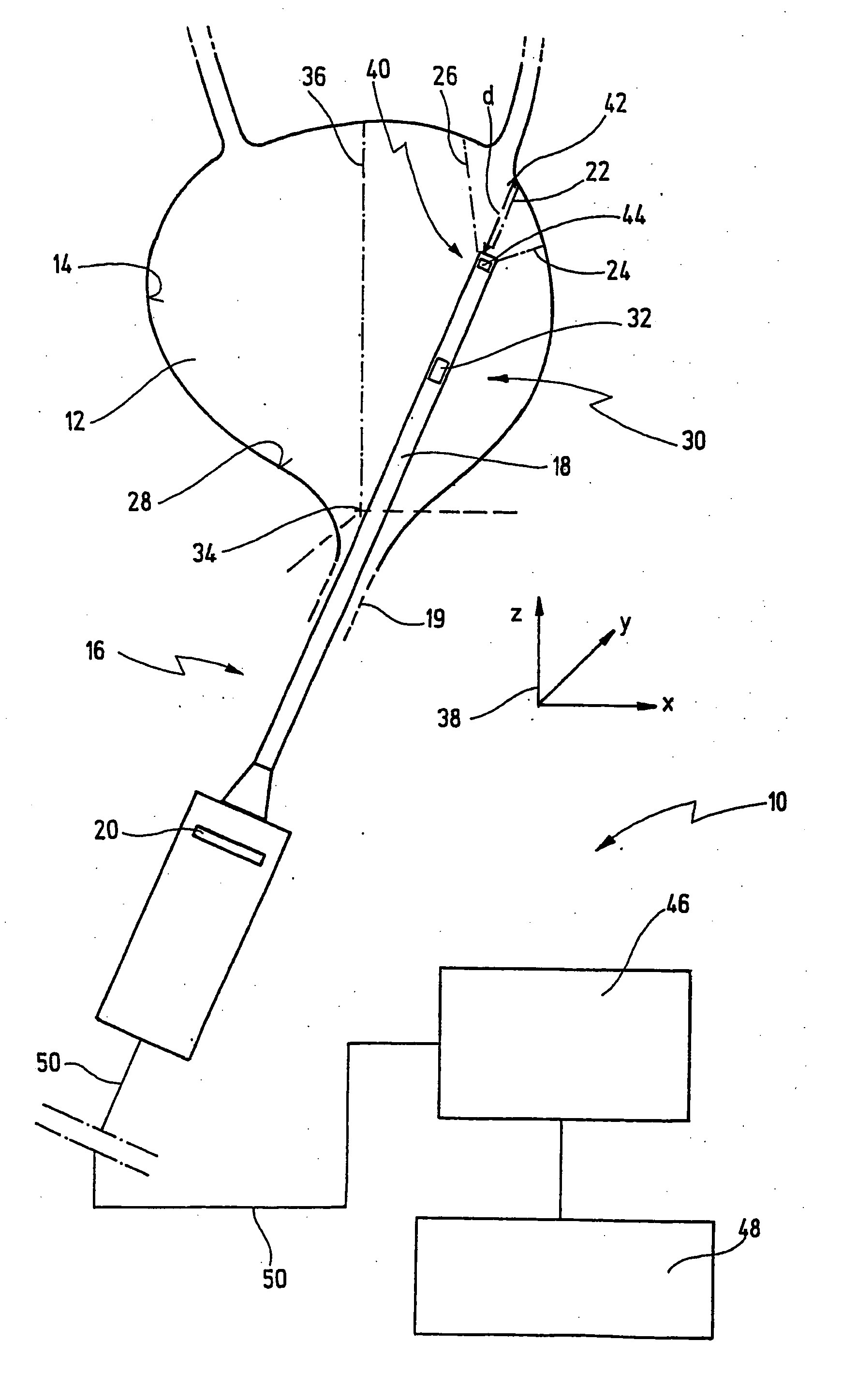
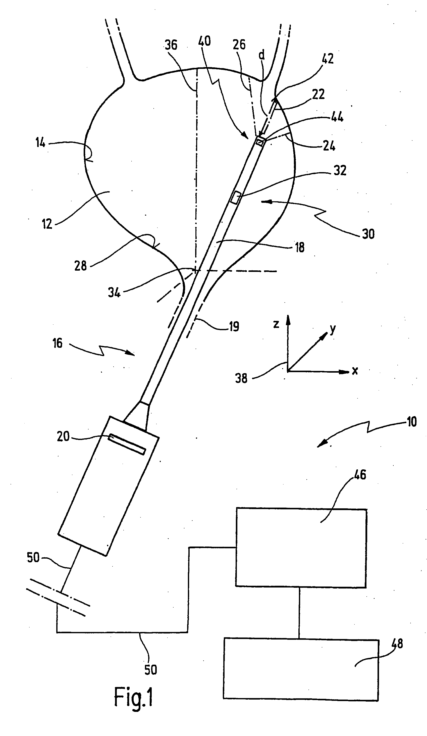
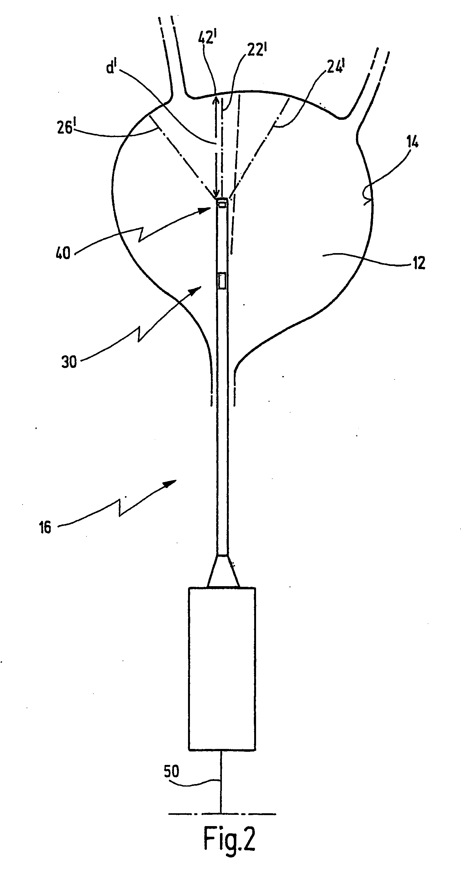
[0053]FIG. 1 illustrates an apparatus, provided with the general reference symbol 10, for at least partially generating a 3D model of a body interior 12. In the exemplary embodiment shown, the body interior 12 is the bladder of a patient. More exactly, the apparatus 10 is used to acquire a surface 14 of the body interior 12 endoscopically in three dimensions. The apparatus 10 enables an endoscopic documentation of the preferably entire surface 14 of the body interior 12, and Is yet to be described hereafter.

[0054] The apparatus 10 has an endoscope 16 with a shaft 18, which endoscope and shaft can be introduced into the body interior 12. In the present exemplary embodiment, in which the body interior 12 is the interior of a bladder, the shaft 18 is introduced into the bladder via the urethra 19.

[0055] The endoscope 16 can be a so called rigid endoscope, that is to say in this case the shaft 18 is rigid, or the endoscope 16 can be a flexible endoscope, the shaft 18 then being of fle...


PUM


Abstract

A method for generating at least one section of a virtual 3D model of a body interior, in particular a hollow organ, uses data that are provided by at least one endoscope introduced into the body interior. The data comprise at least one position and orientation of the endoscope, the at least one position and orientation being as signed at least one distance between the endoscope and the at least one point on a surface of the body interior, and at least one endoscopic image of the surface of the body interior in the region of the at least one point on the surface of the body interior. From the said data relating to a number of different positions and orientations of the endoscope is/are generated the section or sections of the 3D model in superposition with the associated endoscopic image. An appropriate apparatus is also described.

Description

CROSS-REFERENCE TO RELATED APPLICATIONS [0001] The present application is a continuation of pending International patent application PCT / EP2005 / 001316 filed on Feb. 10, 2005 which designates the United States and claims priority of German patent application No. 10 2004 008 164.6 filed on Feb. 11, 2004.BACKGROUND OF THE INVENTION [0002] The invention relates to a method and an apparatus for generating at least one section of a virtual 3D model of a body interior, in particular a hollow organ. [0003] Such a method and such an apparatus are generally applied and / or used in the endoscopic examination of body interiors in the human or animal body. Such a body interior can be, for example, the bladder, the lung, the stomach, the throat, the esophagus, etc. [0004] Without restriction of generality, the present invention is described with reference to the specific application of the examination of the bladder. [0005] In the endoscopic examination of the bladder, the examining doctor attempt...

Claims


Application Information

Patent Timeline
IPC IPC(8): A61B1/00A61B1/04A61B1/307A61B5/107A61B8/12A61B19/00
CPCA61B1/00009A61B1/042A61B5/065A61B5/1077A61B2019/5251A61B19/5212A61B19/5244A61B2019/505A61B2019/5248A61B8/12A61B2034/2048A61B34/20A61B90/361A61B2034/105A61B2034/2051
Inventor DRAXINGER, WOLFGANGNOLL, MARGARITASTEPP, HERBERTIRION, KLAUS M.
Owner LUDWIG MAXIMILIAN UNIV
Why Eureka
Try Eureka