Multifunctional plow blade positioning apparatus and method

a multi-functional, plow technology, applied in the direction of snow cleaning, way cleaning, construction, etc., can solve the problems of affecting affecting the use of plows by individuals, so as to improve the usefulness of plow blades, improve the effect of plow efficiency, and be easy to li

Inactive Publication Date: 2007-03-22
AGRI COVER
View PDF99 Cites 32 Cited by
  • Summary
  • Abstract
  • Description
  • Claims
  • Application Information

AI Technical Summary

Benefits of technology

[0028] It is a further objective of the present invention to provide a system for placing downward force on the plow blade when the plow blade is in use, preferably a resilient elongated apparatus for placing downward force on the plow blade as a substitute for constructing the plow blade out of heavy materials which would be difficult for an individual to lift.
[0029] It is yet another objective of the present invention to provide a method of placing downward force upon the plow blade during snow plowing operations, preferably a method of providing an elongated member, preferably a resilient elongated member, interconnected between the mounting apparatus and the plow blade such that the elongated member places a sufficient amount of downward force on the plow blade during snow plow operations to improve the usefulness of the plow blade in removing snow during such operations, particularly when the plow blade comes into contact with heavy snows that might otherwise begin to cause the plow blade to ride up on the respective mounting uprights.
[0030] It is yet another objective of the present invention to provide an interconnection system for interconnecting the mounting apparatus of the present snow plow to a vehicle that includes a simple swivel apparatus that can pivot horizontally to permit the plow blade to be turned either to the left or to the right of an angle generally perpendicular to the direction of travel of that of the vehicle pushing the plow blade.
[0031] It is still another objective of the present invention to provide a mounting apparatus including at least one mounting upright, the mounting uprights preferably including attachment members for securing the plow blade when the plow blade is not in use for snow plowing operations and the vehicle is used for transit purposes. It is a further object to provide attachment members that allow the plow blade to be easily lifted, one end at a time, and secured in the respective attachments members one end at a time, so that a single individual can easily lift the plow blade up into the non-operational use position without assistance.
[0032] It is yet another objective of the present invention to provide a plow blade including a mold board having attachment channels in which functional parts of the plow blade may be anchored or secured, preferably by securing anchoring nuts within the attachment channel, or attachment channels, in which to secure reciprocally threaded bolts that anchor or secure the functional parts of the plow blade within the attachment channel or channel, such as retention apparatus, preferably a retention member or retention members, a handle or handles for lifting the plow blade and / or hook apparatus, such as a hook or hooks for interconnecting the plow blade to an elongated member attached to the mounting apparatus to provide a downward force on the plow blade during use for snow plowing operations.
[0033] It is yet a further objective of the present invention to provide a plow blade utilizing a mold board including a first and second piece. Preferably, the first and second pieces are interconnected. A two piece construction is more efficient to produce since it requires a smaller die that is available at a greater number of manufacturing facilities.

Problems solved by technology

Moving snow off of open ground, streets, sidewalks and parking lots is an age-old problem in less temperate climates where significant snowfall is anticipated during colder periods of the year.
If the snow is allowed to accumulate over a period of weeks, the snow eventually makes the use of these surfaces for both pedestrian and vehicular travel difficult, if not treacherous.
The purchase and use of such a vehicle by individuals, however, who have a need to move or remove accumulated snow in smaller areas, such as driveways and privately owned parking areas, is less feasible.
First of all, the larger vehicles are expensive to purchase and maintain and are, in some cases, dedicated solely to the removal of accumulated snow.
It will be appreciated that it would not be cost effective for an individual to purchase, house and maintain such a vehicle for just removing snow from driveways and smaller parking lots during a limited period of the year.
Furthermore, these vehicles are difficult to operate and often require significant training or experience operating such vehicles.
Many of the snow plows attached to these vehicles, however, are large and heavy and are not easily attached and removed from the vehicles.
Although each of these inventions has its own advantages, none of them are easy to attach to or remove from the vehicle.
These snow plows also tend to be heavy and cumbersome, and at least somewhat unsightly if one is required, for practical reasons, to keep it attached to the vehicle 24 / 7 for a period of several months during the snow season.
In addition, the prior art snow plows are generally so heavy that they will not ride up when they are on open ground, for instance, but will tear up the ground and remove grass and other plant things often just because of the sheer weight of the plow as it passes along the ground surface.
Also, the prior art snow plows are often virtually impossible for a single person to handle, because of the weight associated with these plows; and plows that appear to be relatively light weight, such as the snow plow described by Knutson et al.
(U.S. Pat. No. 6,240,658), generally have multiple attachment points and do not appear to be highly effective, durable or marketable.

Method used


Image

  • Multifunctional plow blade positioning apparatus and method
  • Multifunctional plow blade positioning apparatus and method
  • Multifunctional plow blade positioning apparatus and method

Examples


Embodiment Construction

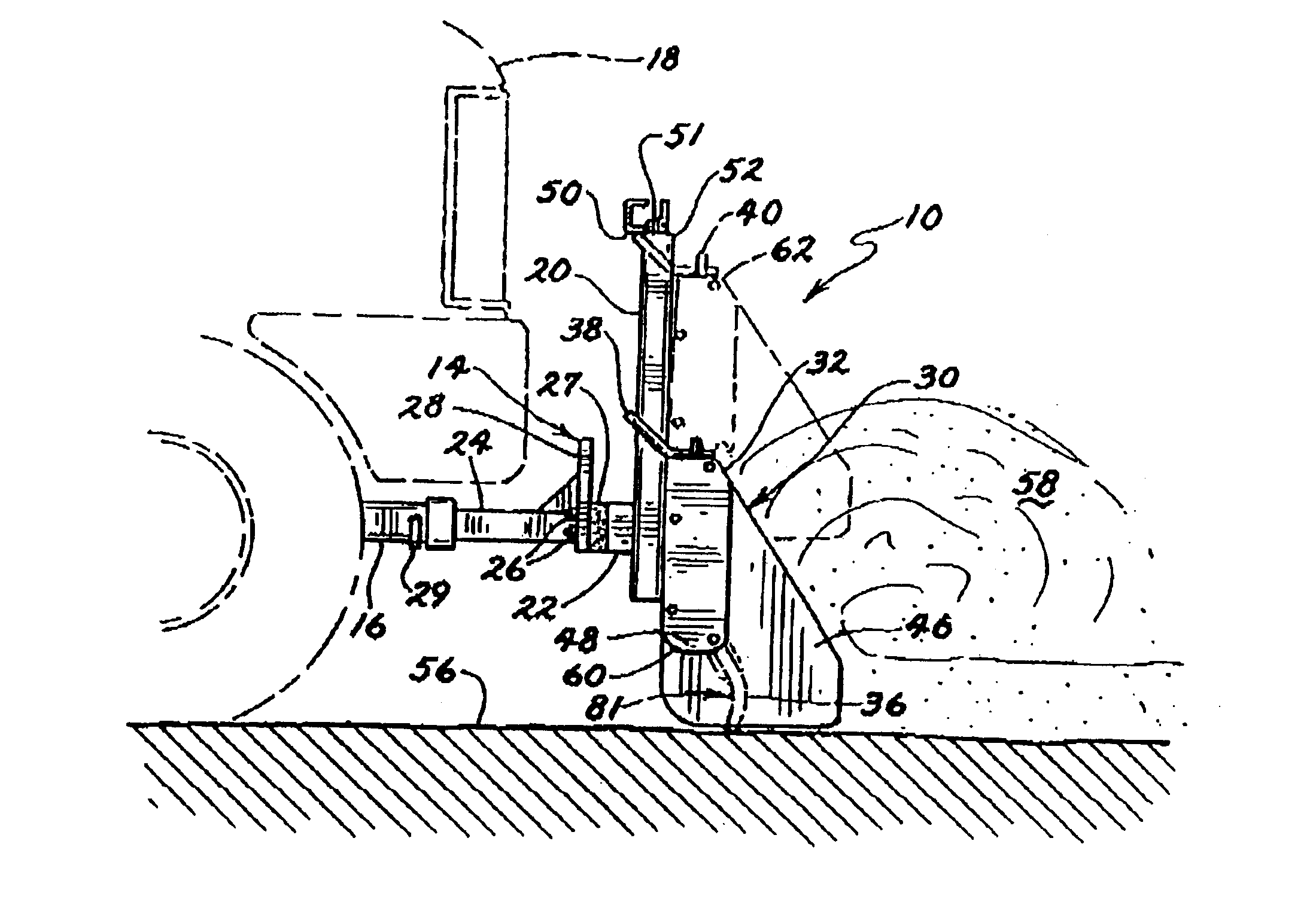
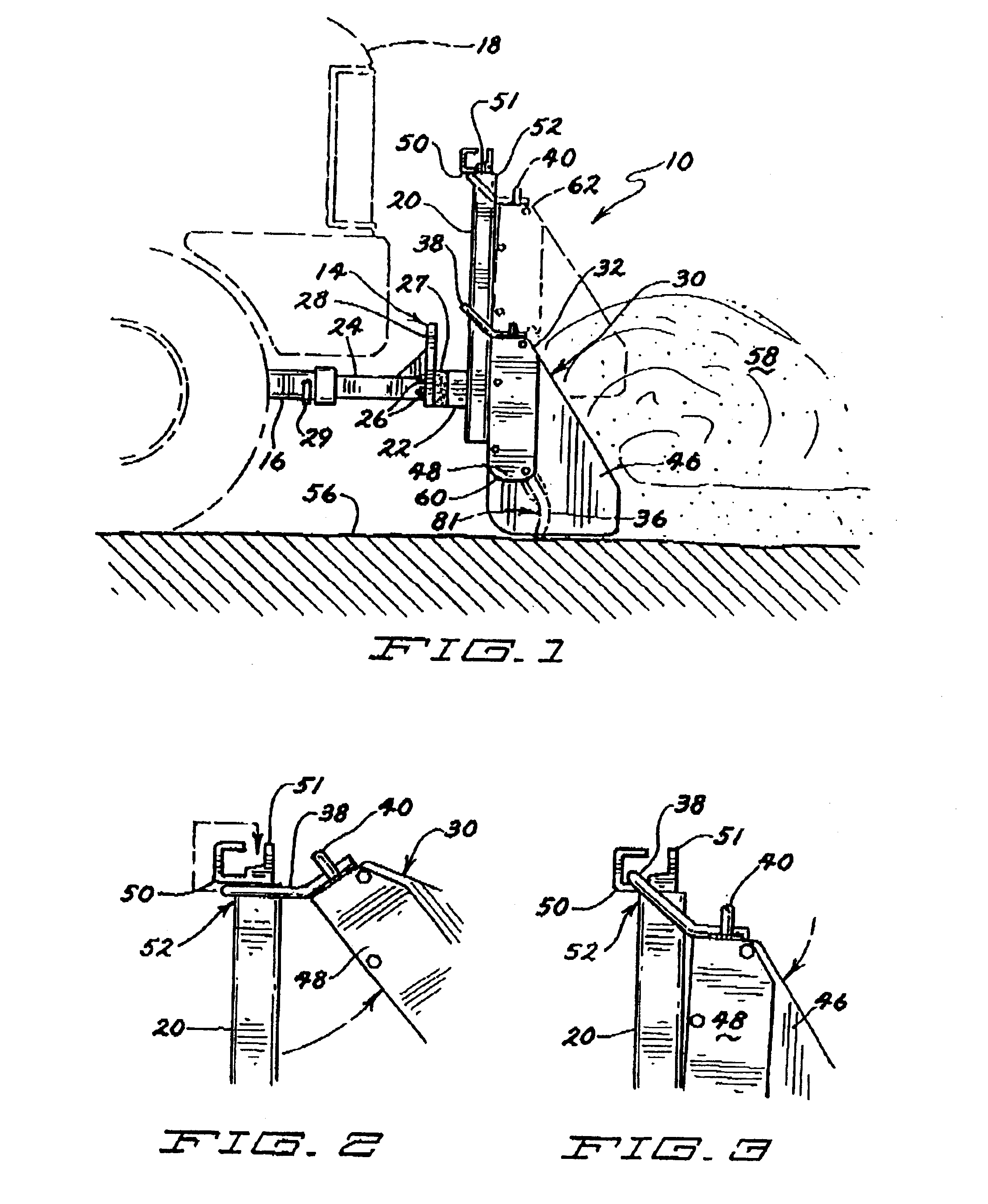
[0099] Referring now to the drawings, and more particularly, to FIGS. 1-3, an alternate embodiment of a self-adjusting snow plow 10 of the present invention is shown. The preferred snow plow 10 includes a mounting apparatus 14 and a plow blade 30. The mounting apparatus 14 of this embodiment includes two mounting uprights 20 that are interconnected by an interconnecting member 22. In this embodiment, a hitch tongue 24 is secured to the interconnecting member 22. The hitch tongue 24 is secured to the interconnecting member 22 with a resilient connecting member 27 located between the interconnecting member 22 and a flat connecting plate 28 of the hitch tongue 24. A hitch tongue securing pin 29 secures the hitch tongue 24 in a hitch receiver 16, which is secured to a vehicle 18 (partially shown in phantom in FIG. 1). The resilient connecting member 27 operates in a manner similar to a motor mount and allows the entire snow plow 10 some flexibility when the plow blade 30 is subjected to...


PUM


Abstract

A self-adjusting snow plow for use with pickup trucks, SUVs, all-terrain vehicles or other land vehicles. The snow plow includes a mounting apparatus for attachment to a vehicle and a plow blade, preferably including a mold board and a retention apparatus assembly. The retention apparatus assembly disengageably secures the plow blade to the mounting apparatus when the plow blade is in a snow displacement position. The snow plow further includes an elongated strap selectively connectable between the plow blade and the mounting apparatus in at least one position, wherein the position is a constrained orientation wherein the elongated strap resists upward movement of the plow blade when the plow blade is disengageably secured to the mounting apparatus or an elevated orientation, wherein the elongated strap suspends the plow blade a desired distance from the ground to prevent the plow blade from contacting the ground and/or snow on the ground.

Description

RELATED APPLICATIONS [0001] The present application is related to and claims priority to pending U.S. patent application Ser. Nos. 10 / 850,151, filed May 19, 2004; Ser. No. 10 / 841,740, filed May 7, 2004 and 10 / 990,148, filed Nov. 15, 2004, each of which claim priority to U.S. patent application Ser. No. 10 / 404,164, filed Mar. 31, 2003, now issued to U.S. Pat. No. 6,817,118, which claims the benefit of PCT Application No. PCT / US01 / 47125 for SELF-ADJUSTING SNOW PLOW filed Nov. 12, 2001, wherein each of the aforementioned applications are incorporated herein by reference.FIELD OF THE INVENTION [0002] The present invention relates to adjustable snow plows for attachment to land vehicles, primarily personal utility vehicles such as pickup trucks and sport utility vehicles. BACKGROUND OF THE INVENTION [0003] Moving snow off of open ground, streets, sidewalks and parking lots is an age-old problem in less temperate climates where significant snowfall is anticipated during colder periods of ...

Claims


Application Information

Patent Timeline
Patent Type & Authority Applications(United States)
IPC IPC(8): E01H5/04
CPCE01H5/06E01H5/062E01H5/061
Inventor SCHMEICHEL, CHARLES M.
Owner AGRI COVER
Why Eureka
Try Eureka