Light emitting diode package and light emitting diode system having at least two heat sinks

a technology heat sinks, which is applied in the direction of semiconductor devices for light sources, lighting and heating apparatus, light source combinations, etc., can solve the problems of loss of photometric efficiency, increase of input power, and increase of junction temperature of light emitting diodes

Inactive Publication Date: 2007-03-22
SEOUL SEMICONDUCTOR
View PDF8 Cites 91 Cited by
  • Summary
  • Abstract
  • Description
  • Claims
  • Application Information

AI Technical Summary

Benefits of technology

[0023] Meantime, an additional heat sink may be arranged along with the at least two heat sinks. A zener diode is mounted on the additional heat sink. The zener diode allows the LED package to be maintained in a constant voltage, thereby protecting the LED package from static electricity or over current.

Problems solved by technology

However, the increase of the input power raises also the junction temperature of the light emitting diode.
The increase of the junction temperature of the light emitting diode causes the loss of photometric efficiency which represents the conversion rate of input energy into visible light.
As a result, power consumption increases considerably.
However, using only one LED die limits the increase of the luminous power.
However, mounting a plurality of LED dies to one heat sink 103 limits an electrical connecting scheme.
However, use of the submount complicates fabrication processes of the LED package and increases manufacturing cost thereof.

Method used


Image

  • Light emitting diode package and light emitting diode system having at least two heat sinks
  • Light emitting diode package and light emitting diode system having at least two heat sinks
  • Light emitting diode package and light emitting diode system having at least two heat sinks

Examples


first embodiment

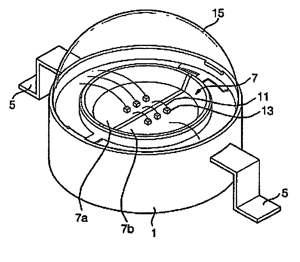
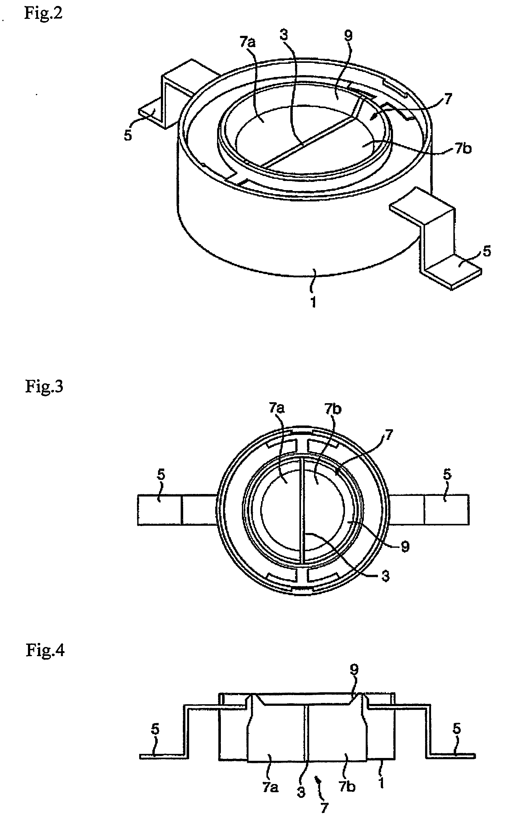
[0054]FIG. 2 is a perspective view illustrating the LED package according to the first embodiment of the present invention, and FIG. 3 and FIG. 4 are a plan view and a cross sectional view illustrating the LED package of FIG. 2, respectively.

[0055] Referring to FIG. 2 to FIG. 4, at least two lead terminals 5 and at least two heat sinks 7 are fixed to a main body 1. The at least two lead terminals 5 comprise a pair of lead terminals 5 electrically coupled to a power source. And the at least two heat sinks 7 may be a pair.

[0056] The main body 1 may be formed by injection molding a plastic resin such as poly carbonate(PC), PCABS, PPA, nylon, polyethyleneterephthalate(PET), polybutyleneterephthalate(PBT), or a model. The main body 1 may be formed in a single body along with at least a septum 3 which electrically isolate the at least two heat sinks 7. In addition, the main body 1 may be attached to the lead terminals 5 and the at least two heat sinks 7 using an insert-molding technique...

second embodiment

[0064]FIG. 6 is a perspective view illustrating an LED package 21 according to the second embodiment of the present invention. And FIG. 7 and FIG. 8 are an exploded perspective view of the FIG. 6 and a cross sectional view of FIG. 6 without lens, respectively. Also, FIG. 9 is a bottom perspective view illustrating a main body of FIG. 6. In the second embodiment, it is described in detail the LED package 21 having three heat sinks and four lead terminals. However, the numbers of the heat sinks and the lead terminals are not limited by the above. That is, it is possible for the LED package 21 to have two heat sinks and three lead terminals, and also the LED package 21 may have much more numbers of heat sinks and lead terminals.

[0065] In FIG. 6 to FIG. 9, lead terminals 51 and heat sinks 41 are fixed to a main body 31, as described referring to FIG. 2 to FIG. 4.

[0066] The main body 31 may be formed by injection molding a plastic resin, as described referring to FIG. 2 to FIG. 4. The ...

third embodiment

[0076]FIG. 11 is a perspective view illustrating an LED package 61 according to the third embodiment according to the present invention.

[0077] Referring to FIG. 11, the lead terminals 51 and heat sinks 81 are fixed to a main body 71, and the LED dies 47a, 47b and 47c are mounted on the heat sinks 81, as described referring to FIG. 6 to FIG. 9. However, the LED package 61 includes an additional heat sink 83, different from the LED package 21 of the second embodiment. Thus, heat-sink receiving recesses, heat-sink binding grooves and septa 75 of the main body 71 are arranged different from those shown in FIG. 6 to FIG. 9. That is, there are provided a receiving recess for receiving the additional heat sink 83 and a binding groove for binding the additional heat sink 83.

[0078] A zener diode 85 is mounted on the additional heat sink 83. The zener diode 85 allows the LED package 61 to be maintained in a constant voltage. Meantime, polychromatic lights from the LED package 61 may be embo...


PUM


Abstract

There is provided a light emitting diode package having at least two heat sinks. The light emitting diode package includes a main body, at least two lead terminals fixed to the main body, and at least two heat sinks of electrically and thermally conductive materials, the heat sinks being fixed to the main body. The at least two heat sinks are separated from each other. Thus, high luminous power can be obtained mounting a plurality of light emitting diode dies in one LED package. Further, it is possible to embody polychromatic lights mounting LED dies emitting different wavelengths of light each other in the LED package.

Description

TECHNICAL FIELD [0001] The present invention relates to a light emitting diode package and a light emitting diode system, and more particularly, to a high power light emitting diode package using a light emitting diode die as a light source, and a light emitting diode system having the high power light emitting diode package. BACKGROUND ART [0002] Recently, it is on the rise to use a light emitting diode (LED) as a light source. More than several thousands lumina of luminous power are, generally, required to use the light emitting diode as a light source for specific applications such as illumination. The luminous power of the light emitting diode is substantially proportional to input power. Therefore, high luminous power is obtained by increasing the electric power inputted to the light emitting diode. However, the increase of the input power raises also the junction temperature of the light emitting diode. The increase of the junction temperature of the light emitting diode cause...

Claims


Application Information

Patent Timeline
Patent Type & Authority Applications(United States)
IPC IPC(8): H01L23/495F21K99/00H01L33/50H01L25/075H01L33/56H01L33/58H01L33/62
CPCH01L25/0753H01L33/642H01L33/647F21Y2113/007H01L2224/48247H01L2224/48091H01L2924/00014H01L2224/49113F21Y2115/10F21Y2113/17
Inventor HAN, KWAN YOUNGPARK, KWANG ILCHO, JAE HOSEO, JUNG HOORYU, SEONG RYEOL
Owner SEOUL SEMICONDUCTOR
Why Eureka
Try Eureka