Liquid ejection head and manufacturing method thereof

Inactive Publication Date: 2007-03-22
FUJIFILM CORP
View PDF2 Cites 36 Cited by
  • Summary
  • Abstract
  • Description
  • Claims
  • Application Information

AI Technical Summary

Benefits of technology

[0013] The present invention has been contrived in view of the foregoing circumstances, an object thereof being to provide a liquid ejection head, and a method of manufacturing a liquid ejection head, whereby the variation in the cross-sectional area of the nozzles can be reduced and image quality can be improved.

Problems solved by technology

In Japanese Patent Application Publication Nos. 6-134994 and 9-216368, in practice, the nozzle length is defined on the basis of the thickness of the active layer of the SOI substrate and / or the dielectric layer, but on the other hand, the reduction achieved in the variation of the cross-sectional area of the nozzles is limited.

Method used


Image

  • Liquid ejection head and manufacturing method thereof
  • Liquid ejection head and manufacturing method thereof
  • Liquid ejection head and manufacturing method thereof

Examples


first embodiment

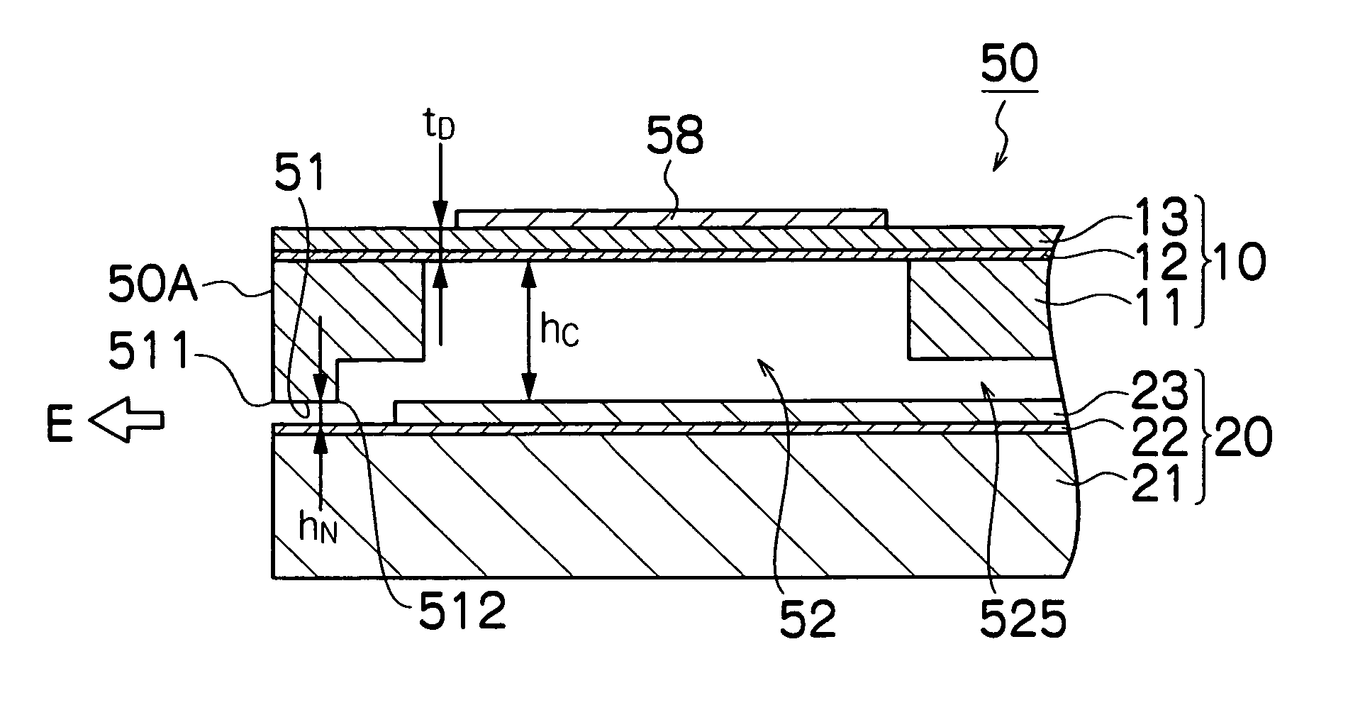
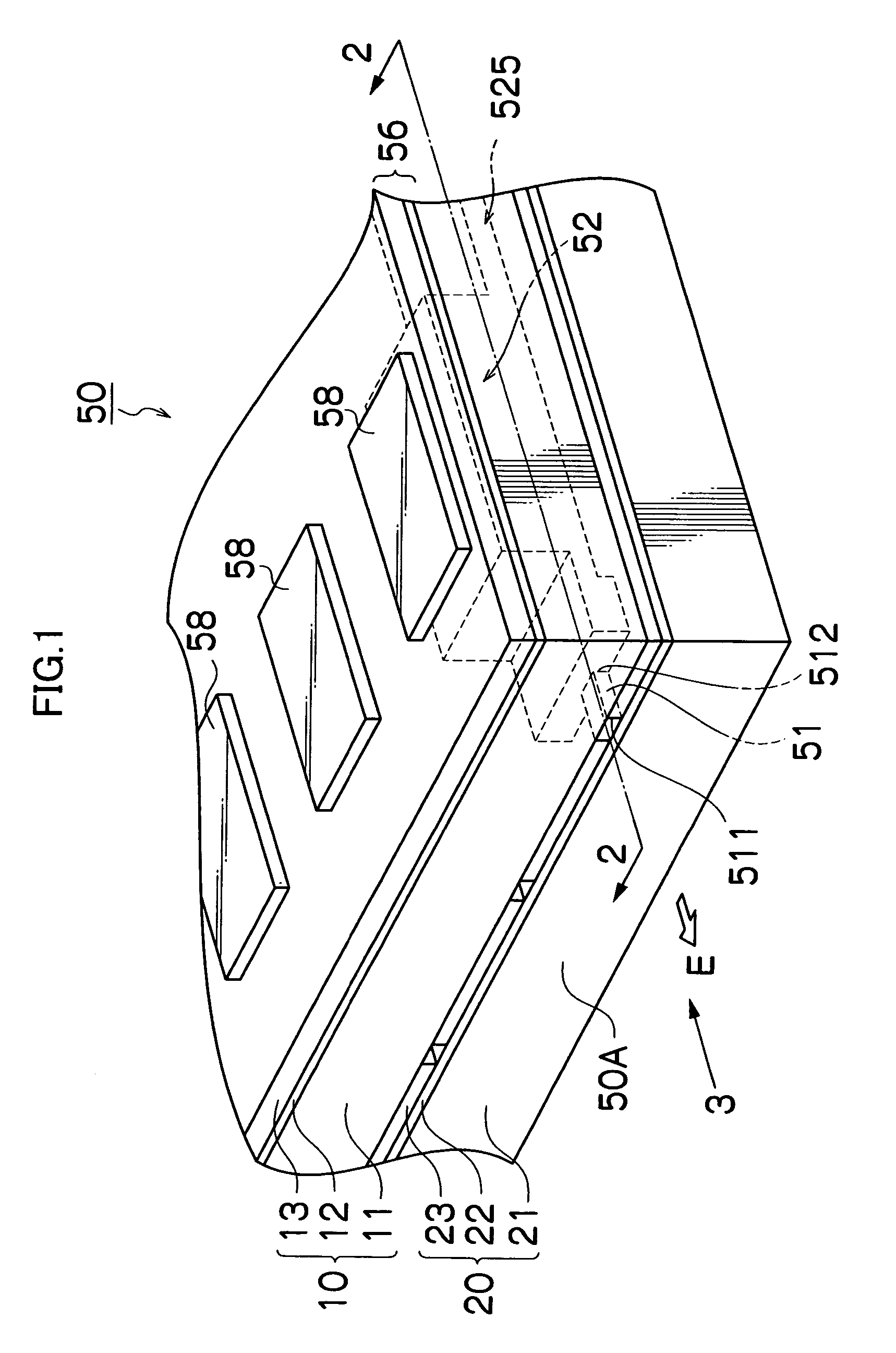
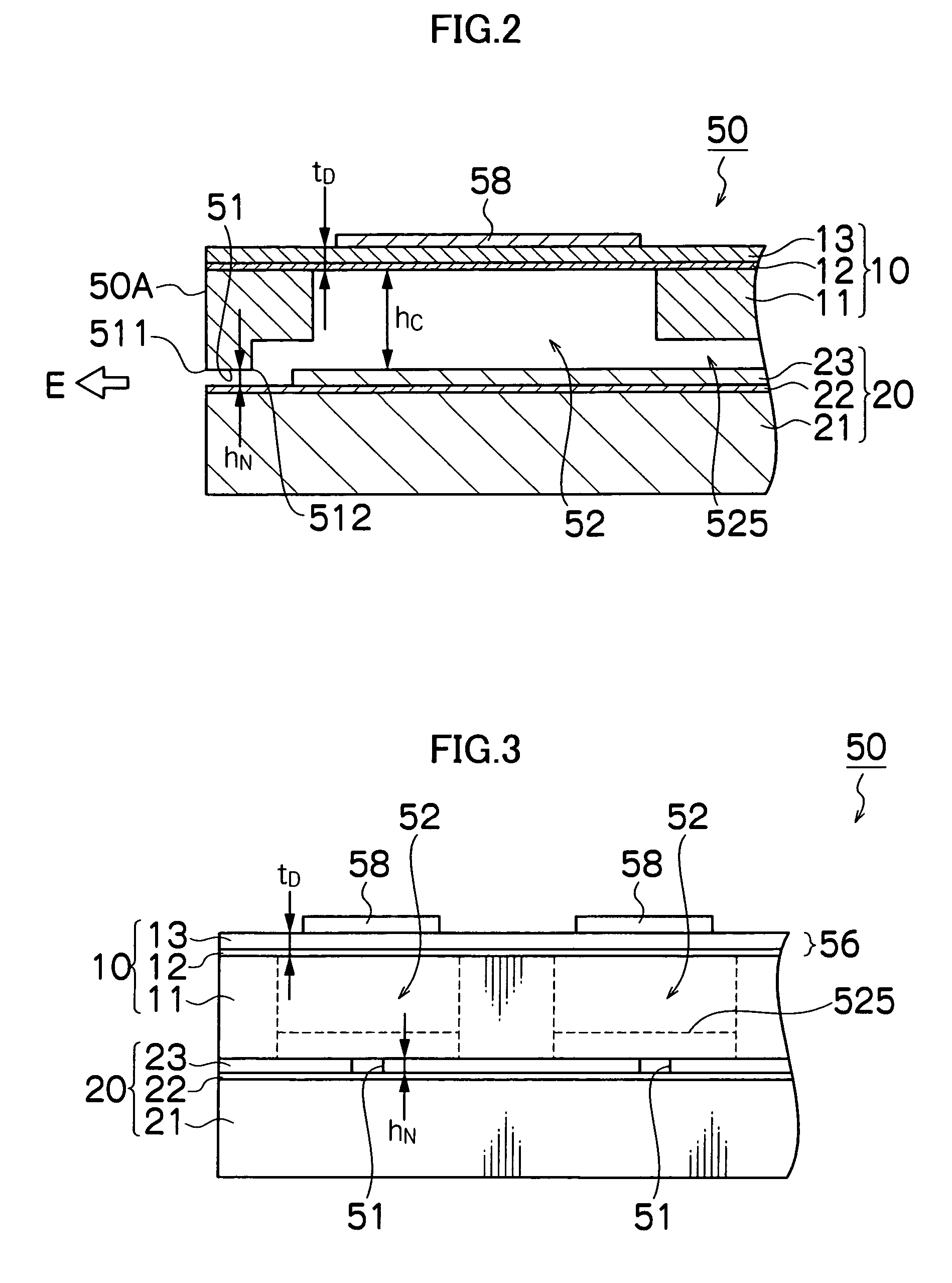
[0043]FIG. 1 is an oblique diagram showing the principal parts of a liquid ejection head 50 according to the present invention. FIG. 2 is a cross-sectional diagram along line 2-2 in FIG. 1, and FIG. 3 is a side view observed in the direction of arrow 3 in FIG. 1.

[0044] The liquid ejection head 50 according to the first embodiment is laminated from at least two SOI (silicon on insulator) substrates.

[0045] The SOI substrate is a plate-shaped member in which a silicon layer is disposed on an insulating layer. More specifically, the SOI substrates 10 and 20 used in the present embodiment are three-layer substrates constituted by forming dielectric layers 12 and 22 made of silica (SiO2) on supporting layers 11 and 21 made of silicon (Si), and then forming active layers 13 and 23 made of silicon (Si) on the dielectric layers 12 and 22, respectively.

[0046] In general, the thickness of the supporting layers 11 and 21 is several hundred micrometers (μm), and the thickness of the dielectric...

second embodiment

[0077]FIGS. 5A to 5G are process diagrams showing a manufacturing process for the liquid ejection head 50 shown in FIGS. 1 to 3.

[0078] In the present embodiment, the piezoelectric elements 58 are formed on the outer surface of the active layer 13 of the first SOI substrate 10, as shown in FIGS. 5A and 5B, and the recesses 520 corresponding to the pressure chambers 52 and the recesses 5250 corresponding to the liquid supply flow channels 525 are formed in the first SOI substrate10, as shown in FIGS. 5C to 5E, whereupon the first SOI substrate 10 is bonded with the second SOI substrate 20 that has been processed separately as shown in FIGS. 5F to 5G, thereby obtaining the liquid ejection head 50 shown in FIG. 2. Here, desirably, the bonding is carried out at room temperature.

[0079] By forming the piezoelectric elements 58 on the outer surface of the active layer 13 of the first SOI substrate 10 in this way, and then forming the recesses 520 below the piezoelectric elements 58, it is ...

third embodiment

[0080]FIGS. 6A to 6G are process diagrams showing a manufacturing process for the liquid ejection head 50 shown in FIGS. 1 to 3.

[0081] In the present embodiment, the recesses 520 corresponding to the pressure chambers 52 and the recesses 5250 corresponding to the liquid supply flow channels 525 are formed in the first SOI substrate 10, as shown in FIGS. 6A to 6D, and the piezoelectric elements 58 are then formed on the outer surface of the active layer 13 of the first SOI substrate 10, as shown in FIG. 6E, whereupon the first SOI substrate 10 is bonded with the second SOI substrate 20 that has been processed separately as shown in FIGS. 6F to 6G, thereby obtaining the liquid ejection head 50 shown in FIG. 2. Here, desirably, the bonding is carried out at room temperature.

[0082]FIG. 7 is a cross-sectional diagram showing the principal part of a liquid ejection head 500 according to a second embodiment, in which a liquid resistant layer 528 is formed on the surfaces of the nozzles 51...


PUM


Abstract

The liquid ejection head includes: a first SOI substrate which has a first active layer, a first dielectric layer and a first supporting layer; a second SOI substrate which has a second active layer, a second dielectric layer and a second supporting layer, the second active layer being bonded to the first supporting layer; and a nozzle which is formed between the first supporting layer and the second dielectric layer, the nozzle ejecting liquid in an ejection direction perpendicular to a thickness direction of the first SOI substrate and the second SOI substrate, a cross-sectional width of the nozzle perpendicular to the ejection direction being defined by a thickness of the second active layer.

Description

BACKGROUND OF THE INVENTION [0001] 1. Field of the Invention [0002] The present invention relates to a liquid ejection head and a manufacturing method thereof, more particularly to a liquid ejection head comprising nozzles which eject liquid, and a manufacturing method thereof. [0003] 2. Description of the Related Art [0004] A liquid ejection head has nozzles which eject droplets of ink toward a recording medium, such as paper. In the liquid ejection head, for example, it is known that by changing the volume of pressure chambers connected to the nozzles by means of actuators such as piezoelectric elements, through a diaphragm which constitutes one wall of the pressure chambers, the ink inside the pressure chambers is ejected from the nozzles. [0005] The quality of the image formed on the recording medium by the liquid ejection head depends on variations in the ejection characteristics, such as the volume and ejection speed of the ink droplets ejected from the nozzles, and the like. ...

Claims


Application Information

Patent Timeline
IPC IPC(8): B41J2/045
CPCB41J2/1606B41J2/161B41J2/1646B41J2/1631B41J2/1642B41J2/1626
Inventor SUGIMOTO, SHINYA
Owner FUJIFILM CORP
Why Eureka
Try Eureka