Roller retainer module

a technology of retainer and roller, which is applied in the direction of rotary bearings, linear bearings, shafts and bearings, etc., can solve the problems of not being taken out smoothly, /b> being interfered, and difficult to accomplish assembly tasks, etc., to achieve enhanced strength, reduce cost, and increase production

Inactive Publication Date: 2007-03-22
HIWIN TECH
View PDF7 Cites 6 Cited by
  • Summary
  • Abstract
  • Description
  • Claims
  • Application Information

AI Technical Summary

Benefits of technology

[0012] It is, therefore, an object of the present invention to provide a roller retainer module, which is manufactured by injection mold. With respect to manufacture of the roller retainer module, mold development concept is introduced and thus the roller retainer module may be mass produced in a rapid manner and reduced in cost.
[0013] It is another object of the present invention to provide a roller retainer module, in which a separation space is manufactured as a cellular form having a symmetric shape and an enhanced strength. The separation space may efficiently fix rollers in position and may ...

Problems solved by technology

Such an assembly task can be not easy and time consuming.
This is because that the separation piece 511 has concaved outer rims and thus the separation piece 511 may be interfered by a core of the mold and may not be taken out smoothly.
In doing this, a complicated transmission mechanism is required.
However, it may be hard make the cylinder drawn out since the sample may wrap tightly the cylinder after being cooled and may ...

Method used


Image

  • Roller retainer module
  • Roller retainer module
  • Roller retainer module

Examples


Embodiment Construction

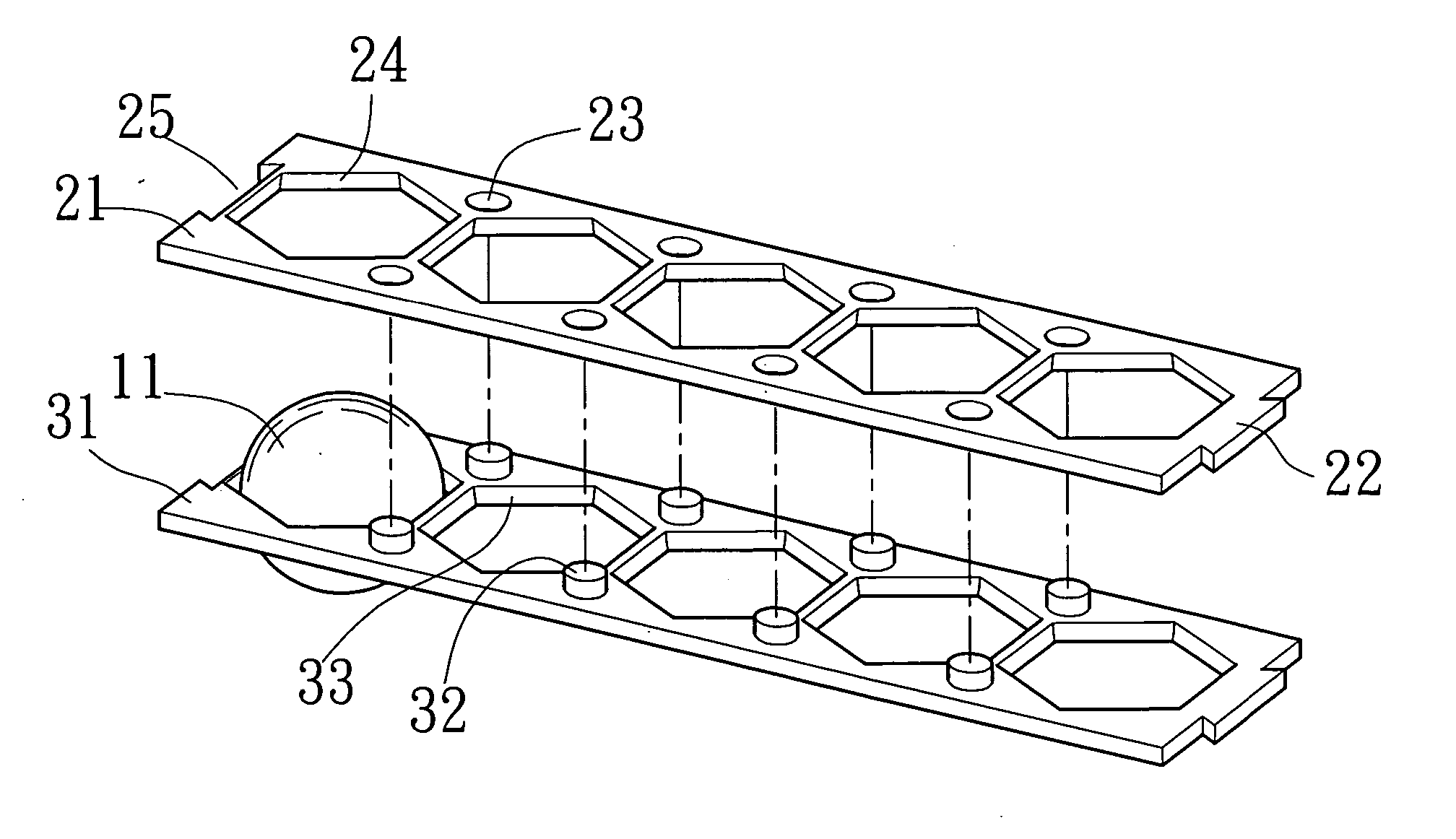
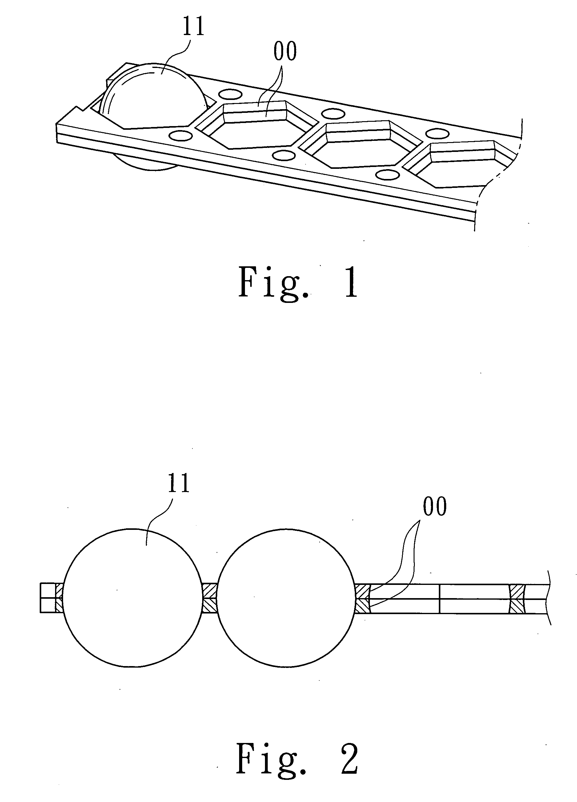
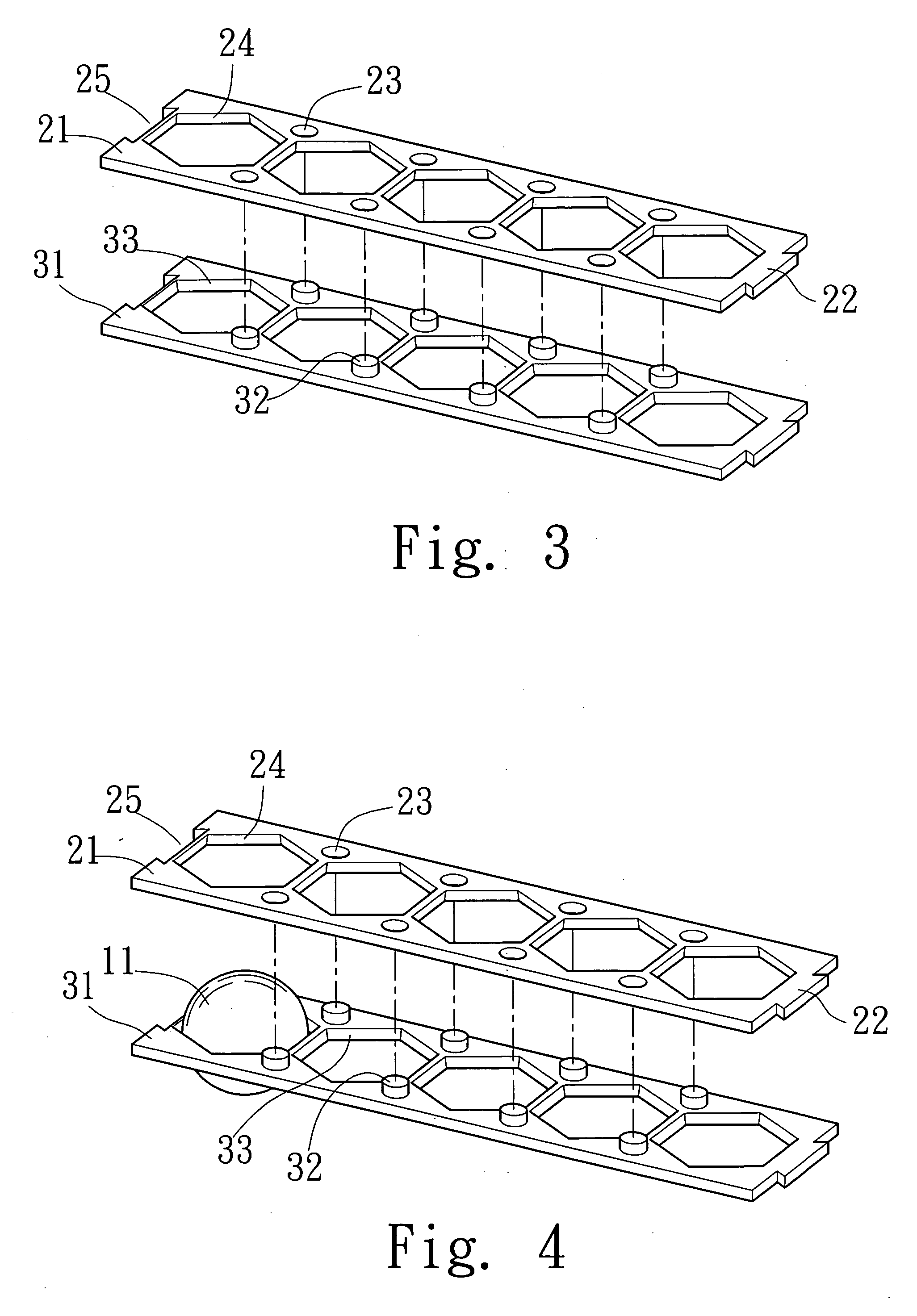
[0025] Referring to FIG. 1 and FIG. 2, a perspective view and cross sectional view of a roller retainer module according to a first embodiment of the present invention are shown therein. As shown, a roller 11 is fixed in position by a retaining and contacting surface 00 and thus refined in a hexagonal cell structure. Specifically, each roller 11 is fixed in the hexagonal cell structure tangent to the retaining and contacting surface 00. In this manner, a friction force between the roller 11 and retaining and contacting surface 00 may be efficiently reduced, enabling the roller 11 to maintain a direction changing ability. Although only a roller 11 is described, the used roller 11 may be more than one and all the rollers 11 are disposed in the same manner as that of the illustrated roller 11.

[0026] Such structure is generally expected to be manufactured in a single body by injection mold. However, this expectation is not viable in terms of development of the mold. This is because the...


PUM


Abstract

A roller retainer module includes an upper and lower thin boards disposed flush with each other, with a plurality of separated space each having a hexagonal cell structure, in which a corresponding roller is fixed in position. Since such cell structure may not exert a large friction force on the roller, the roller may be maintained with its direction changing function.

Description

BACKGROUND OF THE INVENTION [0001] 1. Field of the Invention [0002] The present invention relates to a roller retainer module. More particularly, the present invention relates to a roller retainer used on a straight line transmission member which is used in such as a machine tool, an electronic device and an automatic apparatus. [0003] 2. Description of Related Art [0004] A conventional roller chain can be referred to FIG. 7. As shown, the roller chain 41 has rollers 11 each disposed within a separated space 413. Between two linking chains 412b, a plurality of connection chains 412a are connected to form the elongate chain 41. On each of the connection chains 412a, at least a retainer 411 is formed. The retainer 411 is used to fix the roller 11 in position when the separated space 413 is rolled. In this roller chain 41, although the roller 11 may be fixed in position in directions, denoted as “Q” and “L”, the single retainer 411 may not fix the roller 11 in position in the vertical ...

Claims


Application Information

Patent Timeline
IPC IPC(8): F16C19/00A47B88/00
CPCF16C33/3825F16C29/06
Inventor PAN, PO-LIN
Owner HIWIN TECH
Why Eureka
Try Eureka