Blowing mechanism for column type electric fan

Inactive Publication Date: 2007-03-22
FOK SU TIM
View PDF5 Cites 120 Cited by
  • Summary
  • Abstract
  • Description
  • Claims
  • Application Information

AI Technical Summary

Benefits of technology

[0006] First, only the air ducting assembly is pushed to swing to and fro by the swing mechanism of the column type electric fan, while other components such as the driving motor, the impeller, the power cable, etc., are attached to the housing and do not swing with the air ducting assembly. Therefore, the load of the swing mechanism as well as the noise and the vibration caused by the swing movement would be reduced significantly, which leads to a stable operation. At the same time, the possibility of electric short circuit caused by the wear or breakage of the power cable scrubbed by t

Problems solved by technology

As a result, the swing mechanism operates under high load, and thus the micromotor, the crank, the rod and so on are likely to be worn out.
At the same time, some problems such as vibrating and operation noise are easily to be generated.
Moreover, as the driving motor swings along with the air ducting assembly, the power cable contacts with and is scrubbed by neighbor components,

Method used


Image

  • Blowing mechanism for column type electric fan
  • Blowing mechanism for column type electric fan
  • Blowing mechanism for column type electric fan

Examples


Embodiment Construction

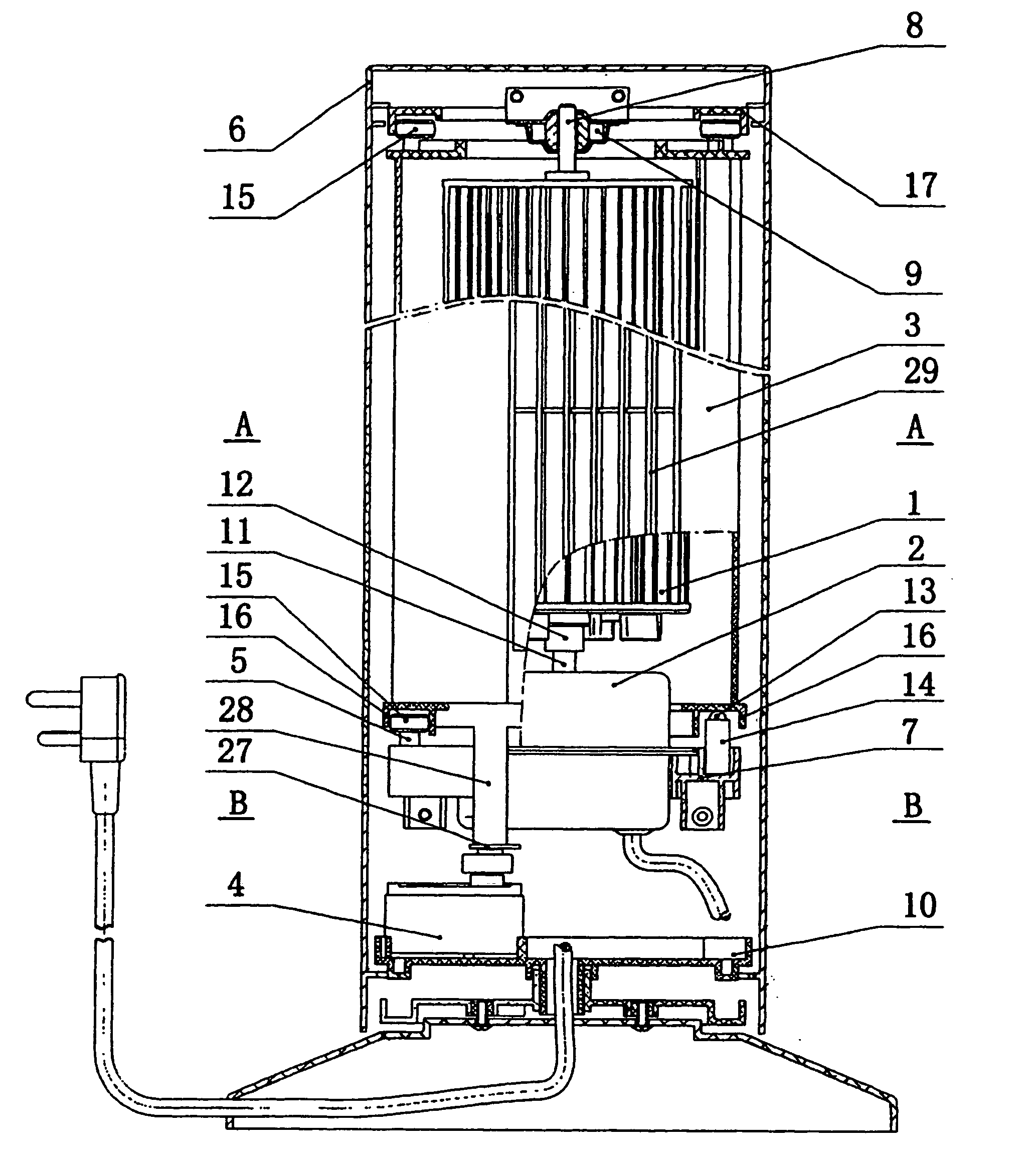
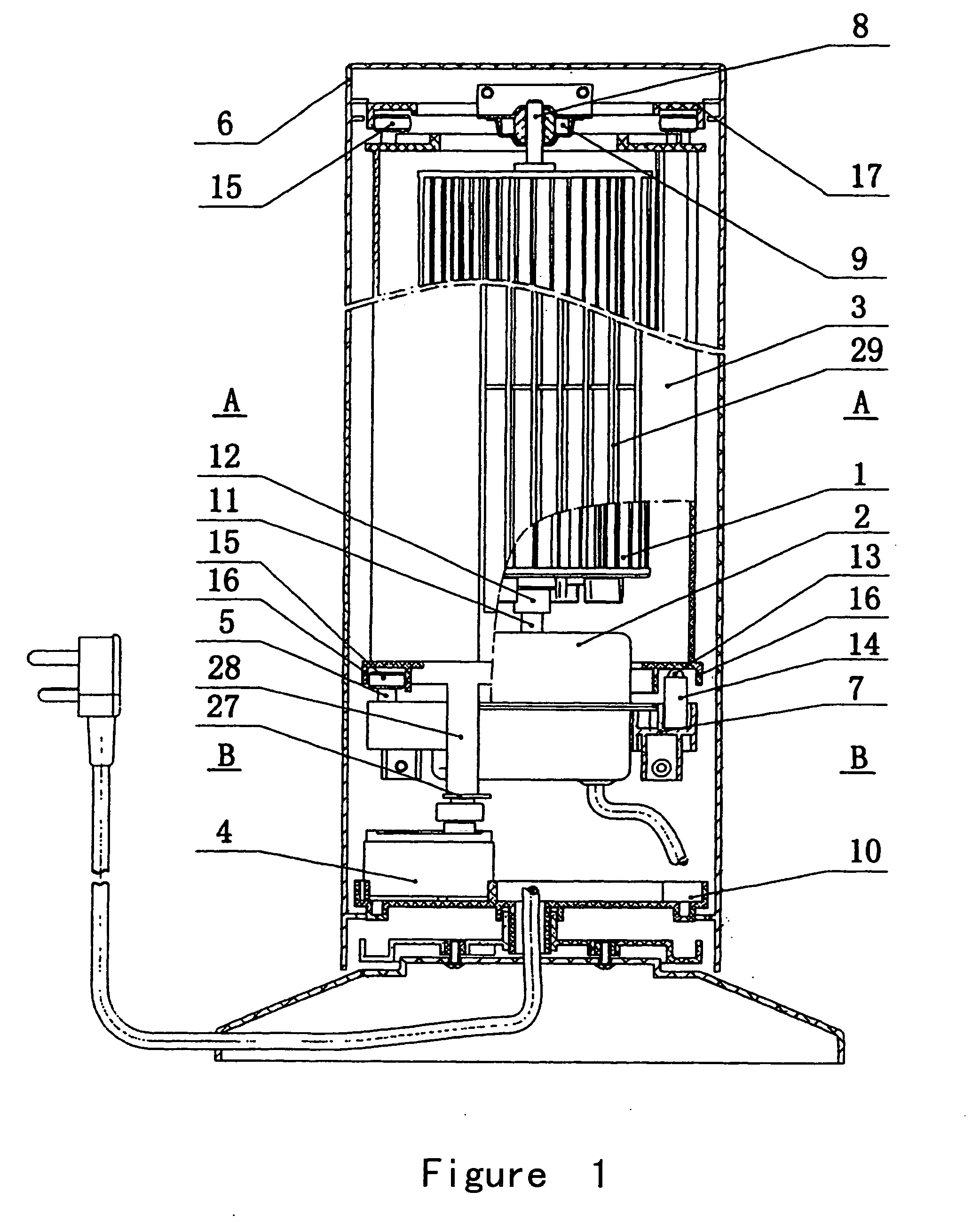
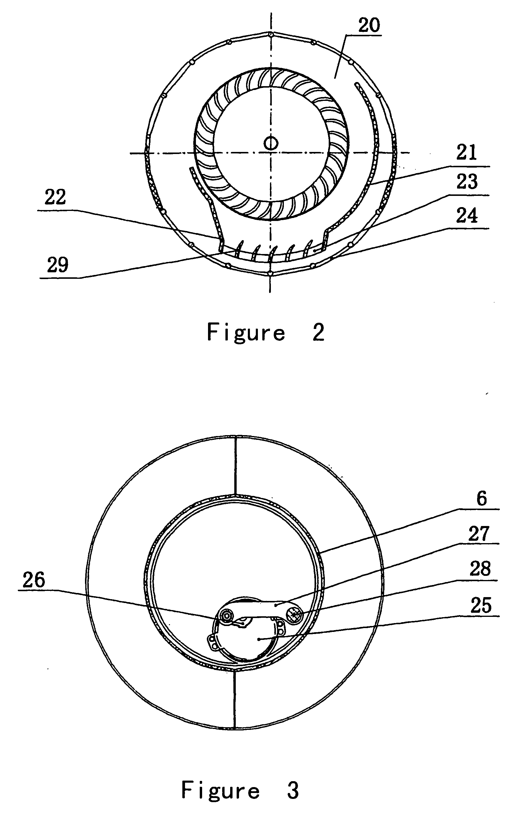
[0013] Referring to the drawings, a blowing mechanism for a column type electric fan, according to the present invention, comprises an impeller 1, a driving motor 2, a tube-like air ducting assembly 3 and a swing mechanism 4. The driving motor 2 is mounted onto a supporting plate 7 which is attached to a housing 6 of the fan. A micromotor 25 of the swing mechanism 4 is fixed onto a connecting disc-like part 10 of the housing 6. A link rod 27 of the swing mechanism is movably connected to a rocker 28 which extends from the lower end of the air ducting assembly 3. The air ducting assembly 3 at least partly encloses the impeller 1 from outside, and an upper supporting shaft 8 of the impeller is rotatably attached to the housing 6 through a bearing 9, while a lower supporting shaft 12 of the impeller is connected to an output shaft 11 of the driving motor. The air ducting assembly 3 comprises a top part 41, a bottom part 42 and a flow guiding plate 21 and a flow deflecting plate 22 conn...


PUM


Abstract

A blowing mechanism for a column type electric fan comprises an impeller, a driving motor, a tube-like air ducting assembly, and a swing mechanism. The driving motor is mounted onto a supporting plate which is attached to a housing of the fan. A micromotor of the swing mechanism is fixed onto a connecting disc-like part of the housing. The air ducting assembly at least partly encloses the impeller from outside. The air ducting assembly comprises a top part, a bottom part and a flow guiding plate and a flow deflecting plate connected between the top part and the bottom part, and is provided with an air inlet and an air outlet. An upper supporting shaft for the impeller is rotatably attached to the housing through a bearing, and a lower supporting shaft for the impeller is connected to an output shaft of the driving motor. A guiding lattice is arranged at the air outlet of the air ducting assembly. Bearing rollers are disposed on the supporting plate. The air ducting assembly is movably carried on the bearing rollers, the air ducting assembly is equipped with retainers for preventing the air ducting assembly from moving beyond desired limit angular positions during its swing motion. A link rod of the swing mechanism is movably connected to a rocker which extends from the air ducting assembly.

Description

FIELD OF THE INVENTION [0001] The present invention relates to a column type electric fan, and more particularly, to a blowing mechanism thereof. BACKGROUND OF THE INVENTION [0002] A known blowing mechanism for a column type electric fan essentially comprises an impeller, a driving motor, a tube-like air ducting assembly, a swing mechanism, etc. The air ducting assembly has an air inlet on one side and an outlet on the other side, and encloses the impeller from outside for collecting tangential air flow generated by the impeller and directing the air flow to the outside. A flow guiding plate and a flow deflecting plate are provided on the opposite sides of outlet. When the impeller rotates, air is sucked into the inlet of the air ducting assembly and is pressurized and discharged to the outside through the outlet. When it is desired for the electric fan to swingingly blow air, the swing mechanism is actuated, and the micromotor of which pushes the main body of the air ducting assemb...

Claims


Application Information

Patent Timeline
IPC IPC(8): F04D29/44
CPCF04D29/703F04D29/462F04D17/04F04D25/10
Inventor FOK, SU-TIM
Owner FOK SU TIM
Why Eureka
Try Eureka