
Switch device

a technology of switch and circuit board, which is applied in the direction of coupling device details, coupling device connection, instruments, etc., can solve the problems of low yield rate, wires must be removed from circuit boards, and it is difficult to setup each computer unit with a separate keyboard, mouse and monitor, etc., to achieve the effect of simplifying line replacement and improving yield ra

Inactive Publication Date: 2007-03-22
EMINE TECH
View PDF9 Cites 1 Cited by
  • Summary
  • Abstract
  • Description
  • Claims
  • Application Information

AI Technical Summary

Benefits of technology

"The invention is a switch device that connects signal lines to a circuit board through a plug and socket combination. This improves yield rate and simplifies line replacement. The switch device has a controlled device that can be switched and connected to different controlled devices through the circuit board. The signal lines are connected to the circuit board through sockets on the signal lines. The electric connections between the signal lines and the circuit board are achieved by way of plug and socket combination. This makes the connection easy and accurate, reduces mistakes in manufacturing process, and improves yield rate of production. The plug and socket also makes the replacement of signal line easy and accurate."

Problems solved by technology

However, it is impractical to setup each computer unit a separated keyboard, mouse and monitor.
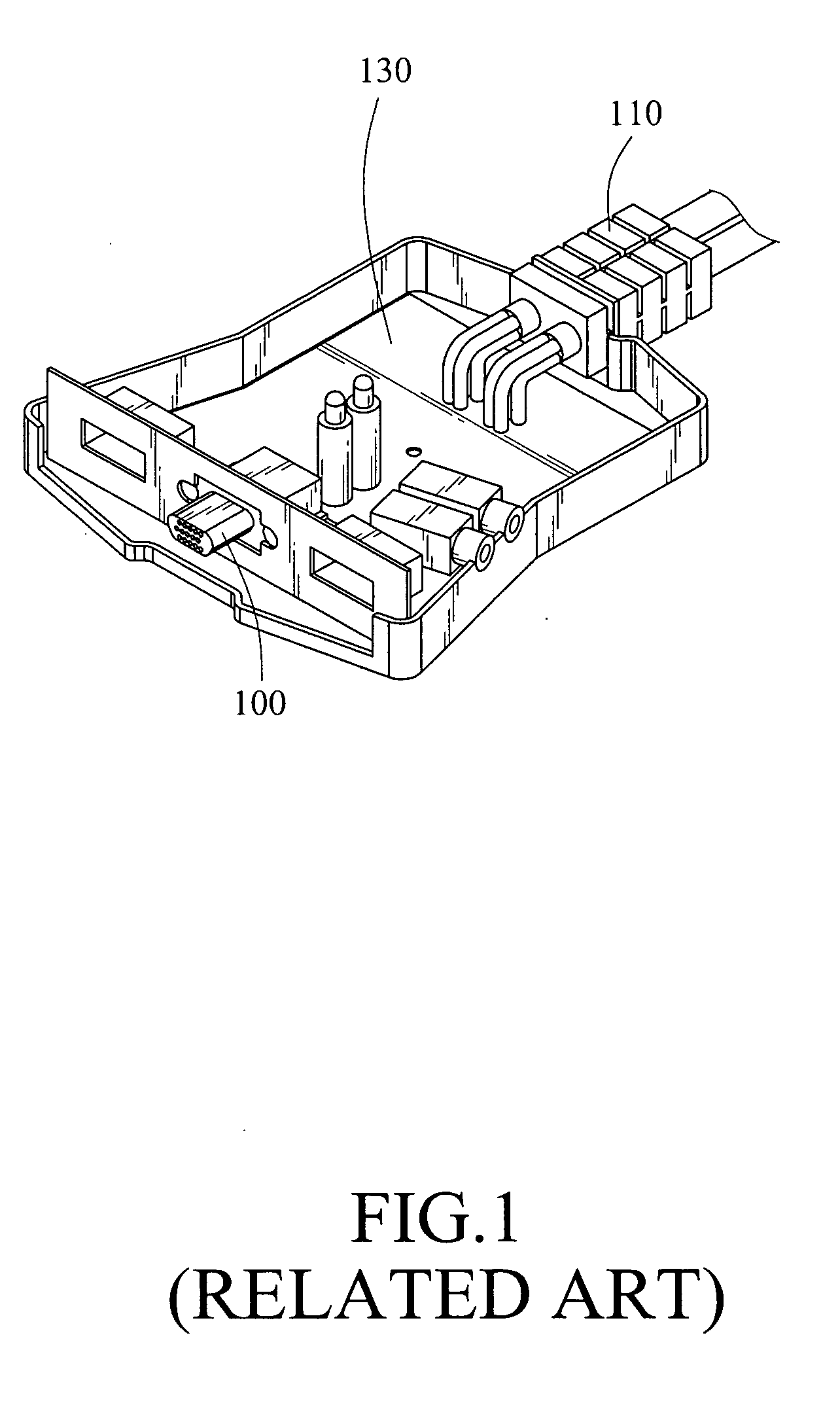
However, since each signal line 110 include many signal wires, the wires in FIG. 1 and aforesaid Taiwan Patent 584276 directly soldered to the circuit boards are easily misallocated, insufficient soldered and caused disconnection and low yield rate.
Moreover, when one repairing a damaged signal line, each wire has to be removed from the circuit board.
Otherwise, wire misallocation will cause futile and repeated efforts.

Method used


Image

  • Switch device
  • Switch device
  • Switch device

Examples


Embodiment Construction

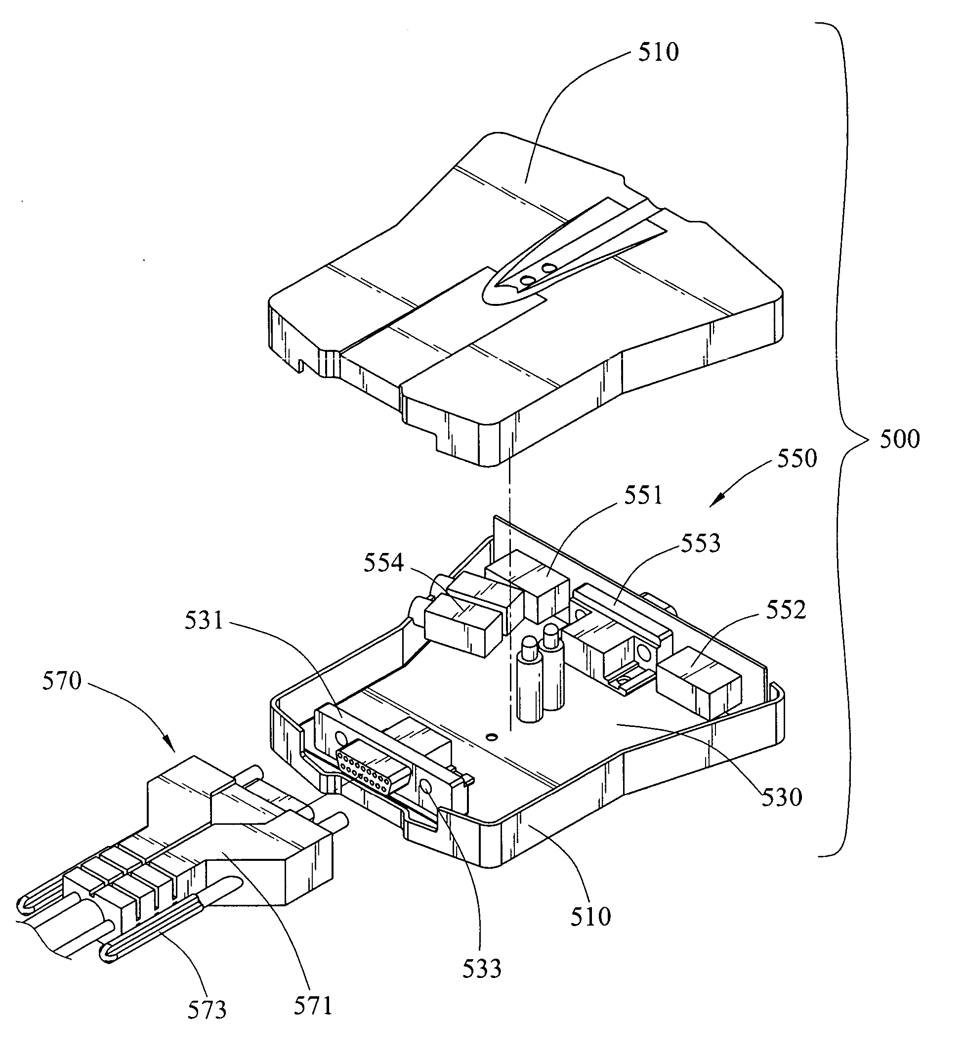
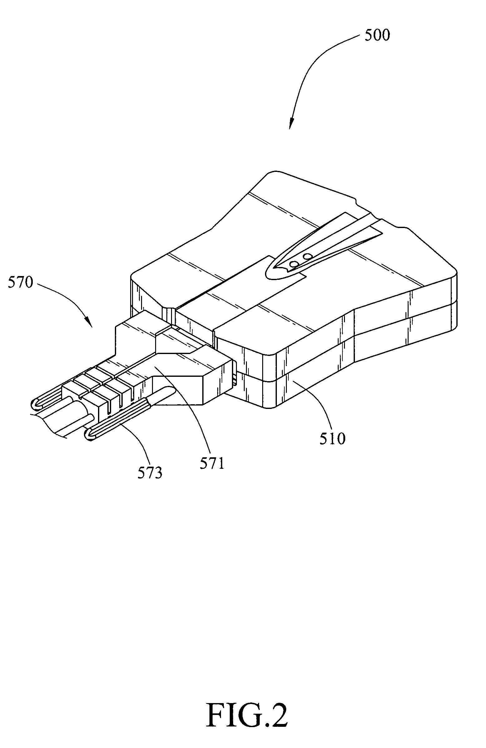
[0018] Please refer to FIGS. 2, 3, and 4, which are a perspective view, an exploded view, and an application diagram of the invention. The switch device 500 of the invention is used to control a plurality of controlled devices from a control element 300. The control element 300 can be a combination of a keyboard 310, a mouse 330, and a monitor 350 and the controlled device 700 can be a computer. The control element 300 is the input / output device of the computer; therefore, different computers, as controlled devices 700, are controlled by the control element 300 via the switch device 500. The function of the switch device 500 is used to switch and connect the control elements 300 to respectively control the different controlled devices 700.

[0019] The switch device 500 includes a circuit board 530 mounted inside a shell 510. The circuit board 530 is composed of electronic components (not shown in the drawing) for performing switch function of switching control signals from the contro...


PUM


Abstract

A switch device makes at least a controlled device controllable by a control element. The control element is connected to signal ports mounted on a circuit board of the switch device. There are signal lines connected between the circuit board and the controlled devices. Besides, the signal lines and the circuit board are connected via a removable plug and socket combination.

Description

CROSS-REFERENCE TO RELATED APPLICATIONS [0001] This non-provisional application claims priority under 35 U.S.C. § 119(a) on Patent Application No(s). 094216008 filed in Taiwan, R.O.C. on Sep. 16, 2005, the entire contents of which are hereby incorporated by reference. BACKGROUND OF THE INVENTION [0002] 1. Field of Invention [0003] The invention generally relates to a switch device, and in particular relates to a switch device for connecting signal lines to a circuit board through a plug and socket combination. [0004] 2. Related Art [0005] For industry computers or server computers, there are possibly many main boards and central processors in the same cabinet. Each group of main board and central processor forms a computer unit. Therefore, in a cabinet there are many computer units. To control the computer units, user has to operate through input / output elements, such as keyboard, mouse and monitor. However, it is impractical to setup each computer unit a separated keyboard, mouse a...

Claims


Application Information

Patent Timeline
Patent Type & Authority Applications(United States)
IPC IPC(8): H05K1/00
CPCH01R13/6215G06F3/023
Inventor HUANG, WEI-CHENHUNG, CHENG-LUNG
Owner EMINE TECH
Learn More