
Non-frequency translating repeater with downlink detection for uplink and downlink synchronization

a repeater and non-frequency translation technology, applied in repeater circuits, line-transmission details, data switching networks, etc., can solve problems such as affecting the operational range of the protocol itself, preventing adequate coverage, and challenging realization of performance levels

Active Publication Date: 2007-03-22
QUALCOMM INC
View PDF94 Cites 60 Cited by
  • Summary
  • Abstract
  • Description
  • Claims
  • Application Information

AI Technical Summary

Benefits of technology

The present invention expands the coverage area of wireless networks such as WLAN, PHS, and TDS-CDMA systems by using a dynamic frequency detection method and repeating method. This allows communication between devices with scheduled or unscheduled transmissions. The repeater can operate in synchronized TDD systems and allow two or more devices to communicate by synchronizing to a control slot interval or any regular downlink interval on a narrow band downlink control channel. The repeater can also monitor one or a number of slots for transmission on the uplink side and repeat the received signal on the uplink channel toward the base station equipment. The repeater provides a direct repeating solution where the received signal is transmitted on the same time slot with minimal delay.

Problems solved by technology

While the specifications of products using the above standard wireless protocols commonly indicate certain data rates and coverage ranges, these performance levels are often challenging to realize.
Problems arise in that structures such as buildings where wireless network support is desired may have floor plans including obstructing wall placements and the like, and may have construction based on materials capable of attenuating RF signals, all of which may prevent adequate coverage.
Lastly, the structure of the protocols themselves may affect the operational range.
However, problems and complications arise in that system receivers and transmitters in any given device may, for example, in a TDD system operate within an allocated time slot.
In such systems, when multiple transmitters operate simultaneously, as would be the case in repeater operation, difficulties may arise.

Method used


Image

  • Non-frequency translating repeater with downlink detection for uplink and downlink synchronization
  • Non-frequency translating repeater with downlink detection for uplink and downlink synchronization
  • Non-frequency translating repeater with downlink detection for uplink and downlink synchronization

Examples


Embodiment Construction

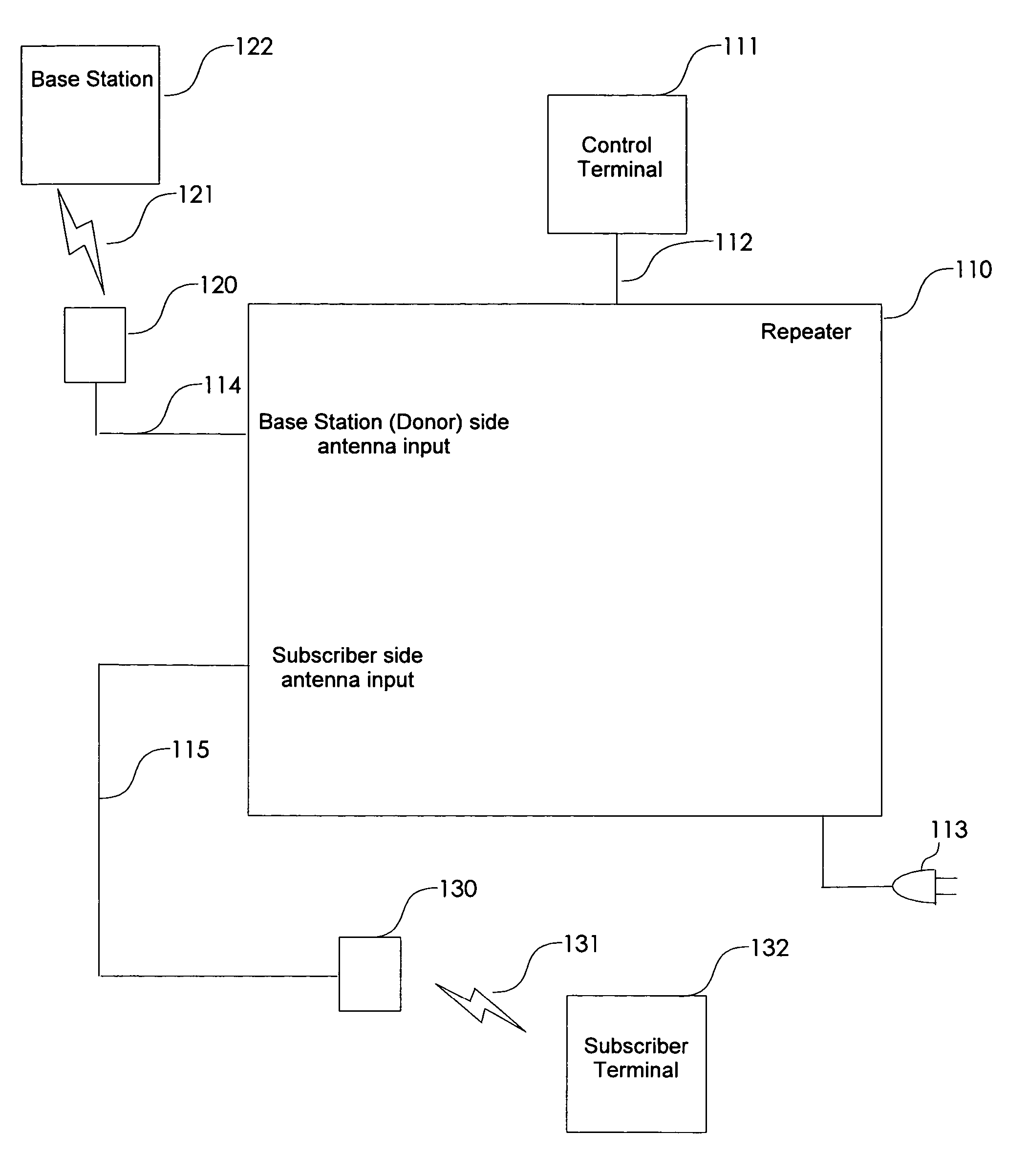
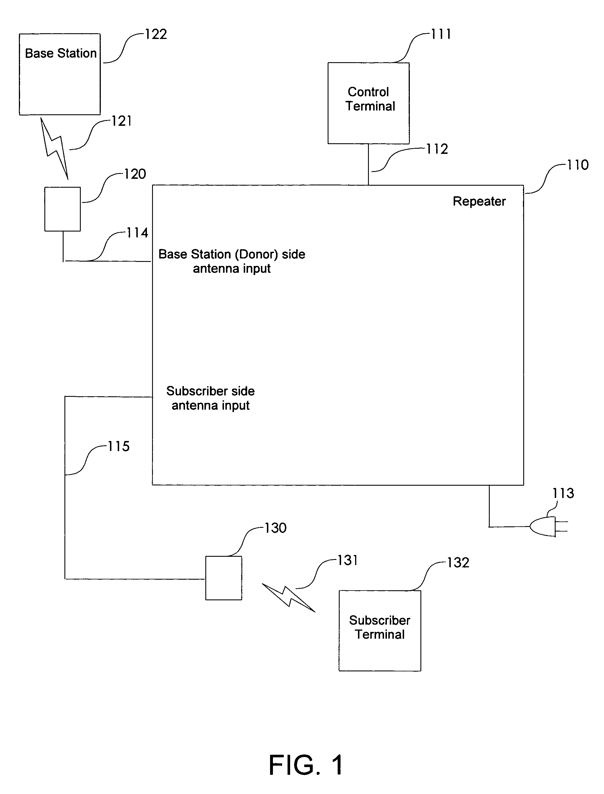
[0018] Referring now to FIG. 1, an exemplary non-frequency translating repeater 110 is shown. The repeater 110 can include a control terminal 111 connected to the repeater 110 through a communication link such as a link 112 which can be a RS-232 connection or the like for conducting serial communication for various purposes such as to configure the repeater 110, collect various metrics, or the like. It will be appreciated that in a production model of the repeater 110, such a connection will not likely be used since the configuration will be completed during manufacturing or the repeater 110 will be automatically configured under control of, for example, a microprocessor, controller, or the like. The repeater 110 system may also include an external antenna 120 for communicating with one side of a TDD repeater connection such as a base station 122 through a wireless interface 121. It will be appreciated that the base station122 can refer to any infrastructure node capable of serving ...


PUM


Abstract

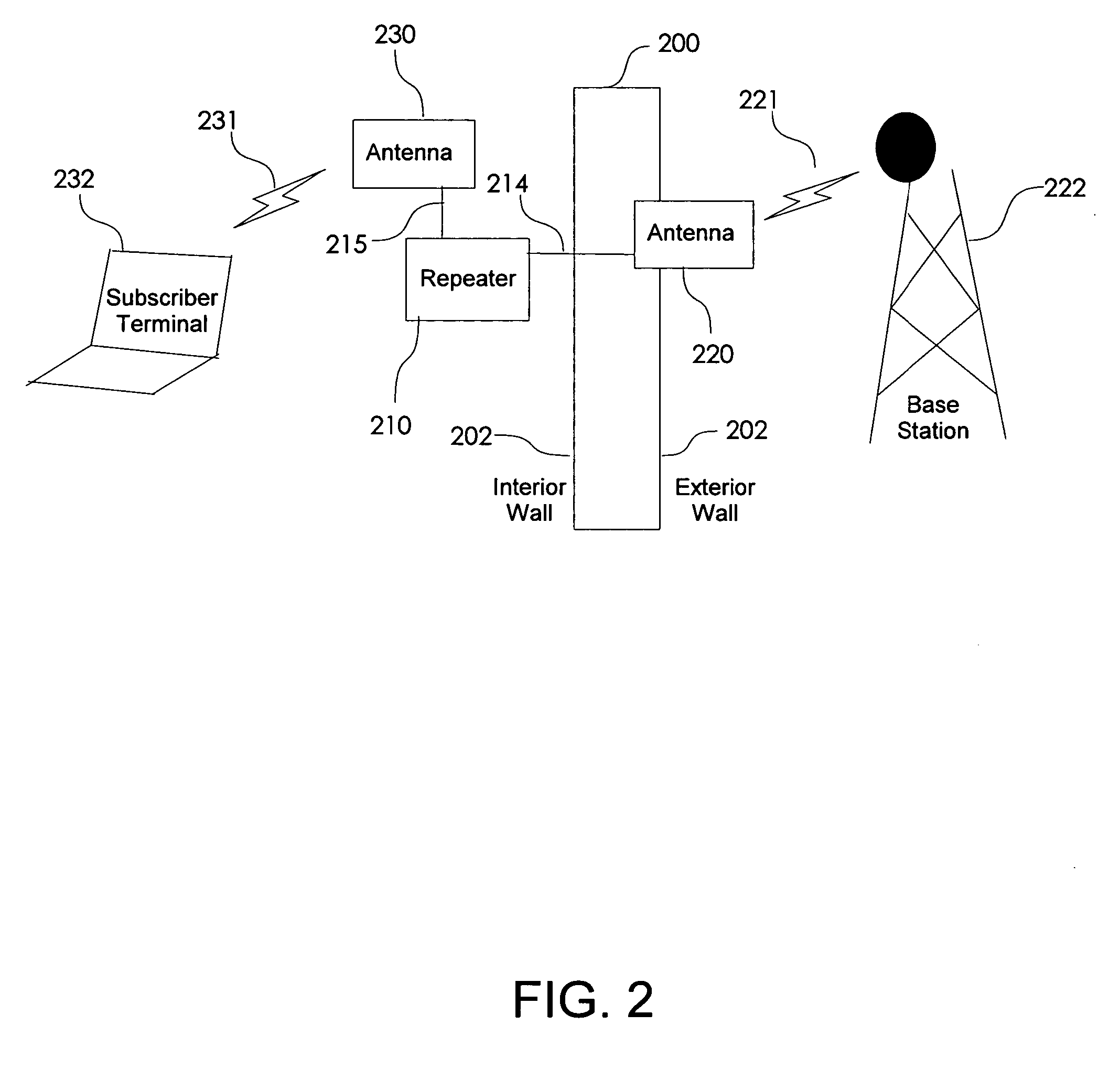
A non-frequency translating repeater (110, 210, 300) for use in a time division duplex (TDD) radio protocol communications system includes detection retransmission and automatic gain control. Detection is performed by detectors (309, 310) and a processor (313). Detection can be overridden by processor (313) using logic elements (314). Antennae (220, 230) having various form factors can be used to couple a base station (222) to a subscriber terminal (232) which can be located in a sub-optimal location such as deep inside a building or the like.

Description

CROSS REFERENCE TO RELATED APPLICATIONS [0001] This application is related to and claims priority from pending U.S. Provisional Application No. 60 / 570,439 filed May 13, 2004, pending U.S. Provisional Application No. 60 / 570,466 filed May 13, 2004, and pending U.S. Provisional Application No. 60 / 570,465 filed May 13, 2004 and is further related to PCT Application PCT / US03 / 28558 entitled WIRELESS LOCAL AREA NETWORK WITH REPEATER FOR ENHANCING NETWORK COVERAGE, and PCT Application PCT / US03 / 35050 entitled WIRELESS LOCAL AREA NETWORK REPEATER WITH DETECTION the contents of which are incorporated herein by reference.BACKGROUND OF THE INVENTION [0002] The present invention relates generally to wireless networks and, particularly, the present invention relates to dynamic frequency and time slot detection and media access control in a non-frequency translating repeater. [0003] Several emerging protocols and / or specifications for wireless local area networks, commonly referred to as WLANs, or ...

Claims


Application Information

Patent Timeline
Patent Type & Authority Applications(United States)
IPC IPC(8): H04B7/15H04B7/155H04B7/26H04L12/28H04L12/56H04W88/04
CPCH04B7/1555H04W88/04H04B7/2606H04B7/14H04B7/15H04B7/212H04W84/08
Inventor PROCTOR,, JAMES A. JR.GAINEY, KENNETH M.SHAD, FAISAL A.
Owner QUALCOMM INC
Learn More