Custom length stent apparatus

a stent and custom technology, applied in the field of medical devices and methods, can solve the problems of requiring an intricate delivery system and being somewhat complex to use, and achieve the effects of facilitating the deployment of the selected group, simplifying the design, and improving the matching of the prosthesis length

Active Publication Date: 2007-03-22
JW MEDICAL SYSTEMS LTD
View PDF99 Cites 125 Cited by
  • Summary
  • Abstract
  • Description
  • Claims
  • Application Information

AI Technical Summary

Benefits of technology

[0012] The invention generally provides for the delivery of prosthetic segments with a flexible delivery catheter capable of navigating torturous vessels such as the coronary arteries. The delivery catheter permits deployment of a selectable number of prosthetic segments at a single treatment site, thus allowing customization of prosthesis length while the delivery catheter is in a body lumen at a treatment sit

Problems solved by technology

Another challenge with existing “custom length” stent delivery systems is that to deliver multiple stent s

Method used


Image

  • Custom length stent apparatus
  • Custom length stent apparatus
  • Custom length stent apparatus

Examples


Embodiment Construction

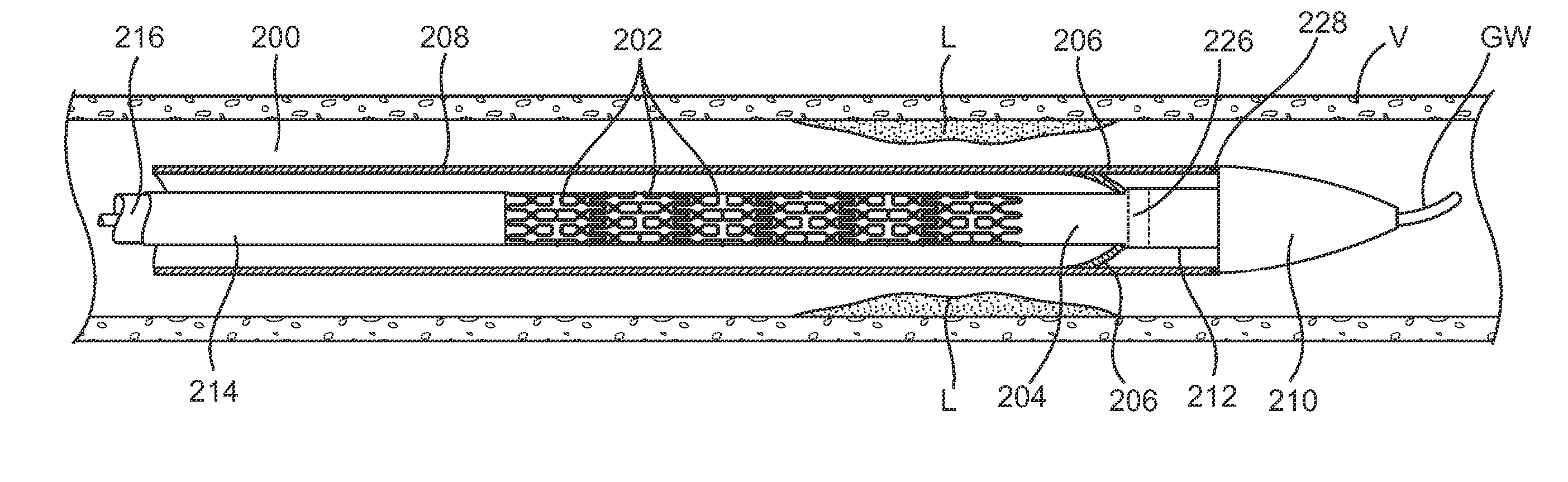
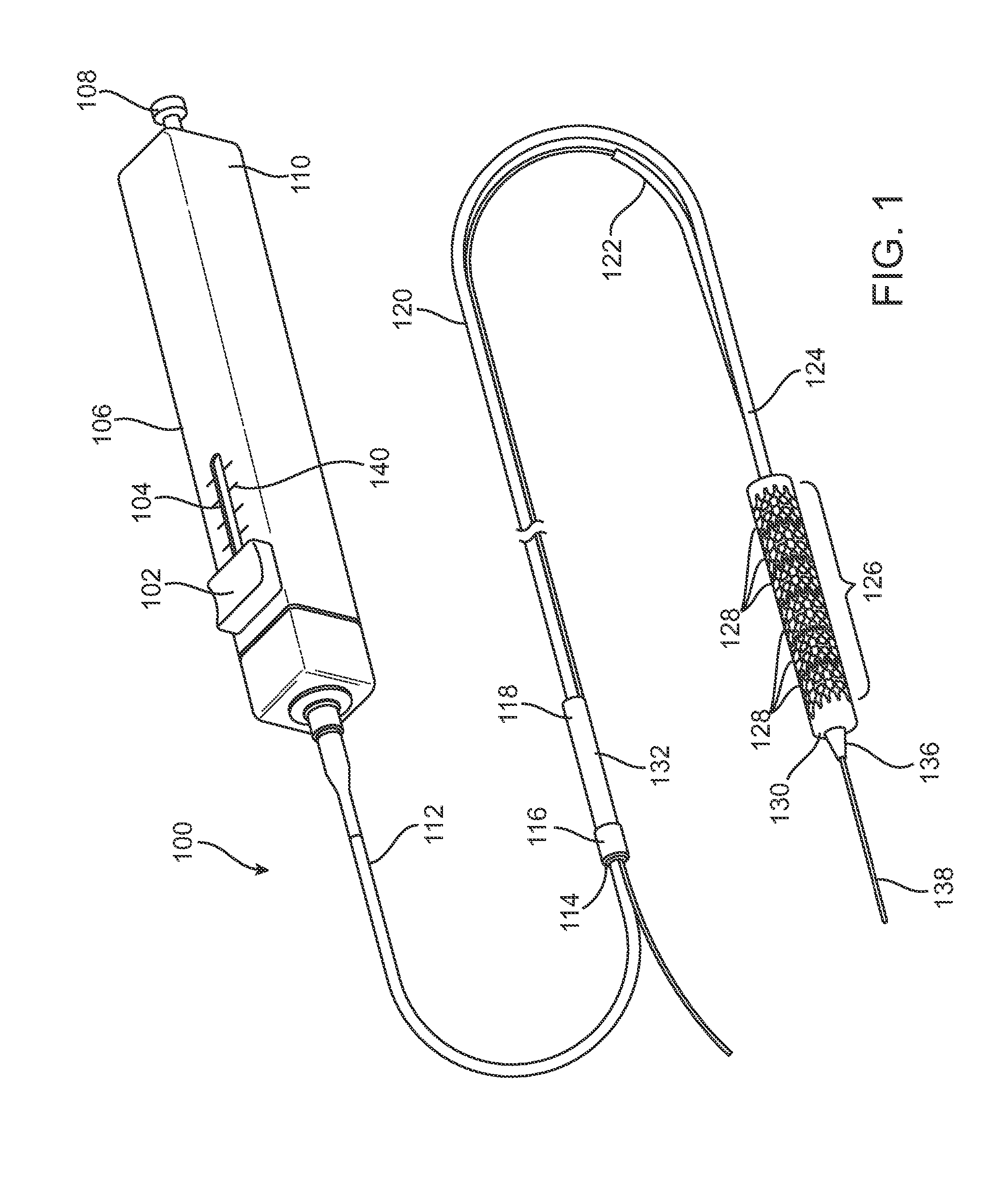
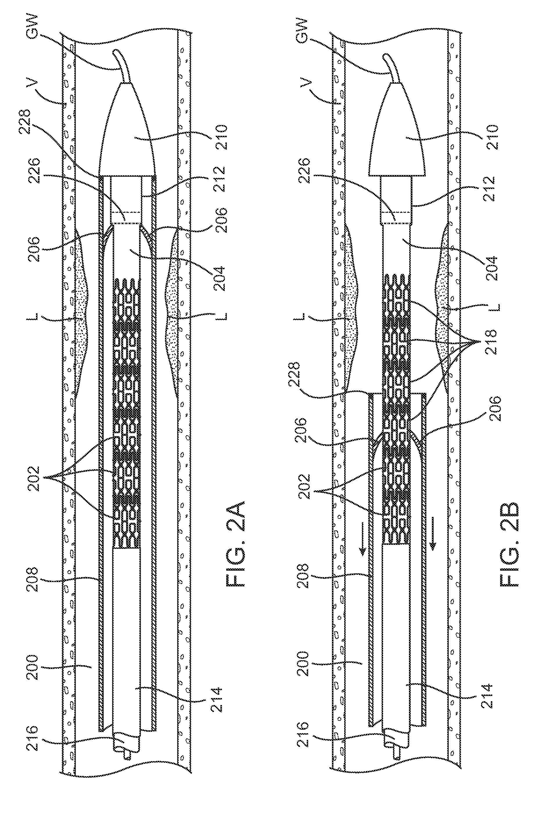
[0043] Referring now to FIG. 1, a stent delivery catheter 100 comprises a catheter shaft 120 with an outer sheath 124 slidably disposed over an inner shaft 216 (seen in FIG. 2A). An inflatable balloon 130, is mounted on the inner shaft 216 and is exposed by retracting sheath 124 relative to the inner shaft 216. A tapered nosecone 136, composed of a soft elastomeric material to minimize trauma to the vessel during advancement of the delivery catheter 100, is attached distally of the inflatable balloon 130 to the inner shaft 216. Prosthesis 126 comprises a plurality of prosthetic segments 128 mounted over the inflatable balloon 130 for expansion. A guidewire tube 122 is slidably positioned through sheath 124 proximal to the inflatable balloon 130. A guidewire 138 is positioned slidably through guidewire tube 122, inflatable balloon 130 and nosecone 136, and extends distally thereof. FIG. 1 illustrates the stent delivery catheter 100 and FIG. 2A shows various elements of the delivery c...


PUM


Abstract

Apparatus and methods for delivering prosthetic segments to a body lumen, utilize a device having an elongated flexible member including proximal and distal ends, a plurality of prosthetic segments releasably arranged axially along the elongated flexible member near the distal end and an outer sheath slidably disposed over at least a portion of the prosthetic segments. The apparatus further includes a separator disposed on the outer sheath and adapted to engage the prosthetic segments. The separator is also adapted to be retracted proximally over the prosthetic segments and advanced distally to separate a proximal group of the prosthetic segments from a distal group of the prosthetic segments which are to be deployed in the body lumen.

Description

CROSS-REFERENCES TO RELATED APPLICATIONS [0001] This application is a continuation-in-part of U.S. patent application Ser. No. 10 / 412,714 (Attorney Docket No. 021629-000330US), filed Apr. 10, 2003, which was a continuation-in-part of U.S. patent application Ser. No. 10 / 306,813, filed Nov. 27, 2002 (Attorney Docket No. 021629-000320US), which was a non-provisional of U.S. Patent Application Nos. 60 / 336,967 (Attorney Docket No. 021629-000300US) filed Dec. 3, 2001, and is also a non-provisional of U.S. Patent Application Ser. No. 60 / 364,389 (Attorney Docket No. 021629-000310US) filed on Mar. 13, 2002, the full disclosures of which are incorporated herein by reference.BACKGROUND OF THE INVENTION [0002] 1. Field of the Invention [0003] This invention relates generally to medical apparatus and methods, and more specifically to vascular catheters, stents and stent delivery systems for use in the coronary arteries and other vessels. [0004] Stenting is an important treatment option for patie...

Claims


Application Information

Patent Timeline
IPC IPC(8): A61F2/84A61F2/00A61F2/82H01Q3/26H04B10/12
CPCA61F2/0095A61F2230/0091A61F2/915A61F2/95A61F2/958A61F2002/826A61F2002/828A61F2002/91508A61F2002/91533A61F2002/9583A61F2210/0033A61F2210/0042H01Q3/2676H04B10/2575A61F2/91
Inventor GEORGE, ROBERTSNOW, DAVID W.CARRISON, HAROLD F.ACOSTA, PABLO
Owner JW MEDICAL SYSTEMS LTD
Why Eureka
Try Eureka