
Deinterleaver and dual-viterbi decoder architecture

a dual-viterbi and decoder technology, applied in the field of wireless communication systems, can solve the problems of signal at specific frequencies being particularly susceptible to disruption, signal at specific frequencies providing insufficient bandwidth for particular communications, and uwb-ofdm communication systems, however, may require significant processing of transmitted and received information

Active Publication Date: 2007-03-22
REALTEK SEMICON CORP +1
View PDF12 Cites 68 Cited by
  • Summary
  • Abstract
  • Description
  • Claims
  • Application Information

AI Technical Summary

Benefits of technology

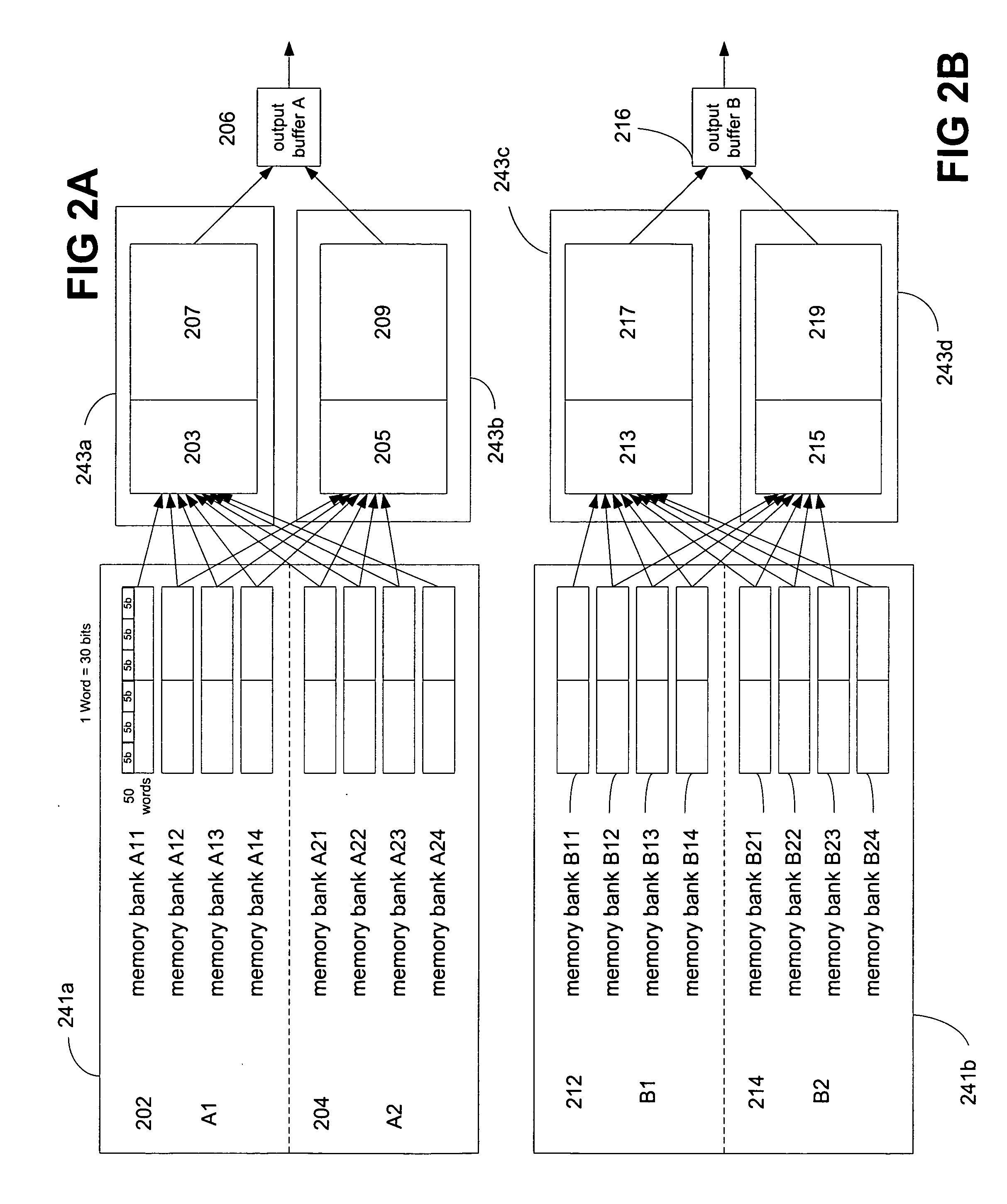
The invention is a system for deinterleaving and decoding data. It includes a deinterleaver that breaks down data and stores it in separate memory banks. The data is then decoded by a pair of Viterbi decoders that access the memory banks at different times. The number of decoding steps taken by the Viterbi decoders is equal to the length of the data in bits. This system allows for faster and more efficient data decoding.

Problems solved by technology

Signals at specific frequencies may be particularly subject to disruption due to interference caused by multipath effects, other transmitters or other factors.
Also, signals at specific frequencies may provide insufficient bandwidth for particular communications.
UWB-OFDM communication systems, however, may require significant processing of transmitted and received information.
Processing tools such as encoders, interleavers, and decoders are not designed for rapid processing of high rates of data.
As a result, data processing in UWB-OFDM communication systems may become time consuming.

Method used


Image

  • Deinterleaver and dual-viterbi decoder architecture
  • Deinterleaver and dual-viterbi decoder architecture
  • Deinterleaver and dual-viterbi decoder architecture

Examples


Embodiment Construction

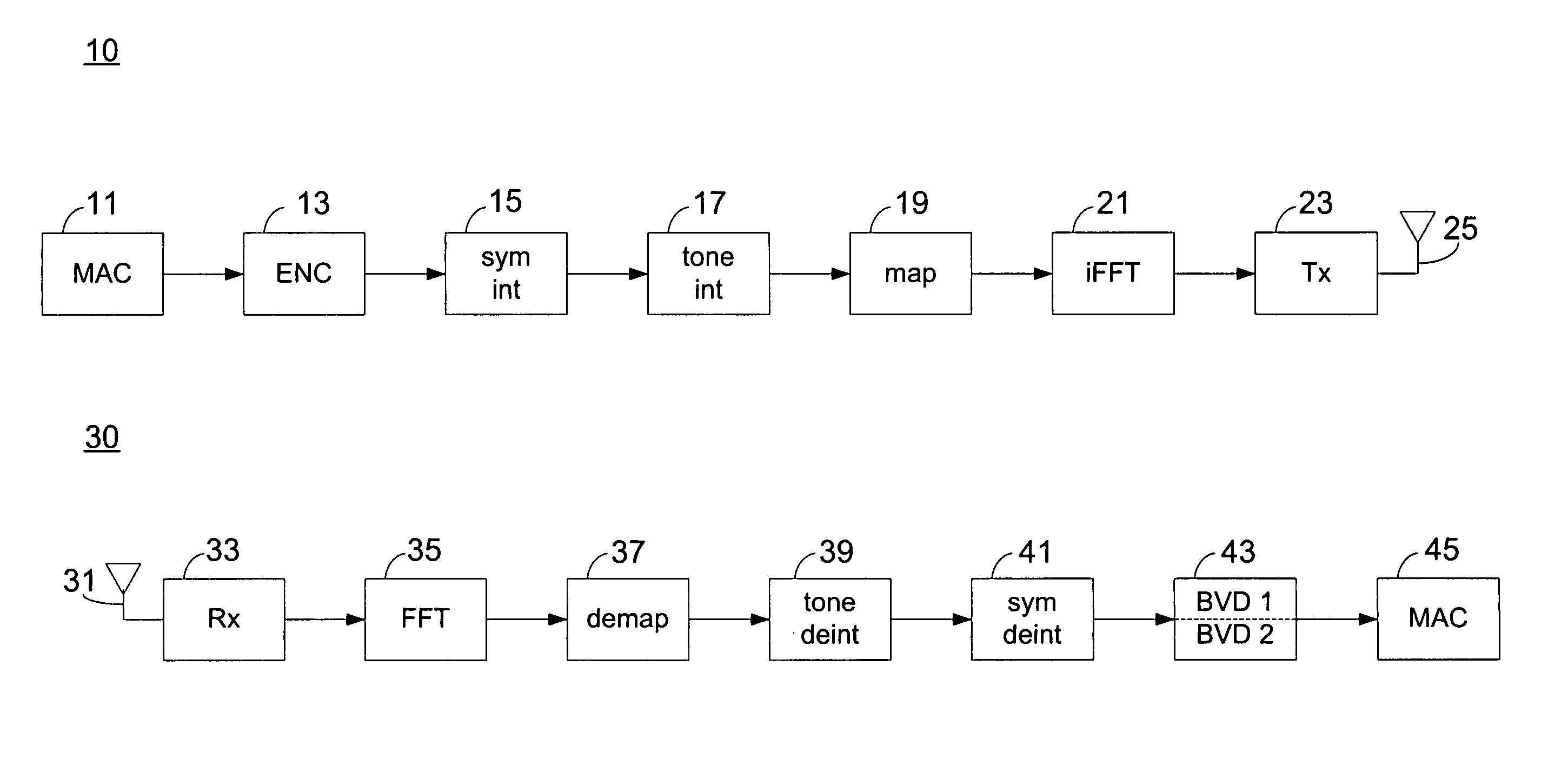
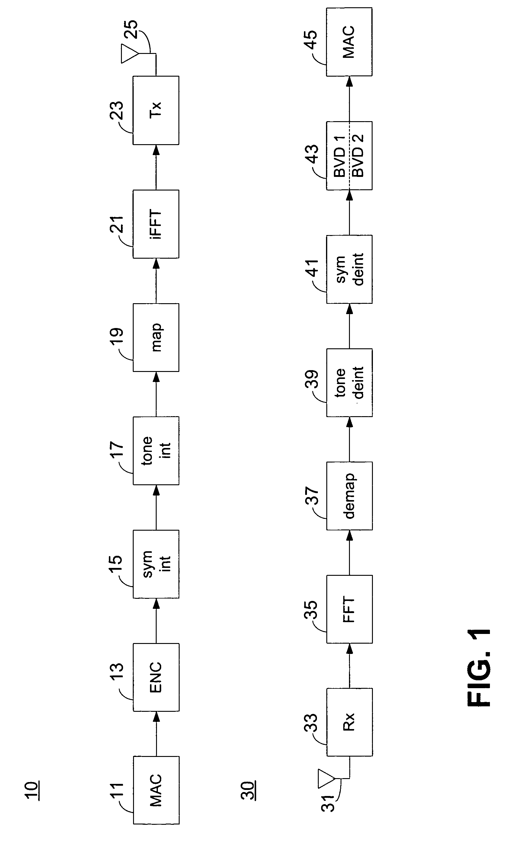
[0016]FIG. 1 is a block diagram of a transmitter 10 and a receiver 30 in accordance with aspects of the invention. The transmitter 10 includes a media access control (MAC) 11 coupled to an encoder 13, a symbol interleaver 15, a tone interleaver 17, a mappers 19, an iFFT block 21, and an analog RF block 23, all in series. The analog RF block 23 transmits the data over a transmitter antenna 25. A stream of data is provided by the MAC 11. The MAC 11 may provide data in the form of bytes or words. The encoder 13 operates on the data. The symbol interleaver 15 receives the data from the encoder 13 and interleaves the received data. The tone interleaver 17 receives the data stream from the symbol interleaver 15. The mapper 19 receives the tone interleaved data and maps or modulates the interleaved data according to a mapping scheme. The mapper may map data using various modulation schemes such as a quadrature phase shift key (QPSK) modulation scheme, a dual carrier modulation (DCM) scheme...


PUM


Abstract

Pairs of parallel Viterbi decoders use windowed block data for decoding data at rates above 320 Mbps. Memory banks of the deinterleavers feeding the decoders operate such that some are receiving data while others are sending data to the decoders. Parallel input streams to every pair of decoders overlap for several traceback lengths of the decoder causing data input to a first decoder at the end of an input stream to be the same as the data input to a second decoder of the same pair at the beginning of an input stream. Then, the first decoder is able to post-synchronize its path metric with the second decoder and the second decoder is able to pre-synchronize its path metric with the first. Either, the deinterleaver data length is an integer multiple of the traceback length or the data input to only the first block of the first interleaver is padded.

Description

CROSS-REFERENCE TO RELATED APPLICATION(S) [0001] This application claims the benefit of the filing date of U.S. Provisional Patent Application No. 60 / 701,680, filed Jul. 21, 2005, the disclosure of which is incorporated by reference herein.BACKGROUND OF THE INVENTION [0002] The present invention relates generally to wireless communication systems, and more particularly to a deinterleaving and decoding method and system useful with ultrawideband orthogonal frequency division multiplexing (UWB-OFDM) communication systems. [0003] Wireless communication systems, generally radio frequency (RF) communication systems, often communicate using signals about a specific predetermined carrier frequency. Signals at specific frequencies may be particularly subject to disruption due to interference caused by multipath effects, other transmitters or other factors. Signals at specific frequencies may also dominate use of bandwidth about the specific frequencies, leaving less of the frequency spectru...

Claims


Application Information

Patent Timeline
Patent Type & Authority Applications(United States)
IPC IPC(8): H03M13/03
CPCH03M13/27H03M13/41H03M13/6561H03M13/6566H04L1/06H04L1/0059H04L1/0068H04L1/0071H04L1/0054
Inventor ALTINTAS, MUSTAFAAYTUR, TURGUTMAHADEVAPPA, RAVISHANKAR H.SHI, FENGBRINK, STEPHAN TENYAN, RAN
Owner REALTEK SEMICON CORP
Learn More