Turbine exhaust catalyst

a catalyst and turbine technology, applied in the direction of turbine/propulsion engine ignition, combustion types, heat recovery, etc., can solve the problems of less effective, reduced catalyst temperature, and excessive pressure in the enclosure, so as to optimize the catalyst effectiveness and reduce the temperature of the exhaust gases. , the effect of low enclosure pressur

Active Publication Date: 2007-03-29
M ITSUBISHI POWER AERO LLC
View PDF9 Cites 35 Cited by
  • Summary
  • Abstract
  • Description
  • Claims
  • Application Information

AI Technical Summary

Benefits of technology

[0005] Briefly, in accordance with one aspect of the invention, instead of the catalyst bed being placed across the enclosure, the catalyst bed is placed immediately downstream of the gas turbine exhaust such that the primary exhaust air passes through the catalyst prior to ...

Problems solved by technology

It has been recognized that if a catalyst bed is introduced in such an arrangement, that both the turbine exhaust gases and the cooling air pass through the catalyst bed, then the pressure drop through the catalyst would cause excessive pressure rise in the enclosure and r...

Method used


Image

  • Turbine exhaust catalyst
  • Turbine exhaust catalyst

Examples


Embodiment Construction

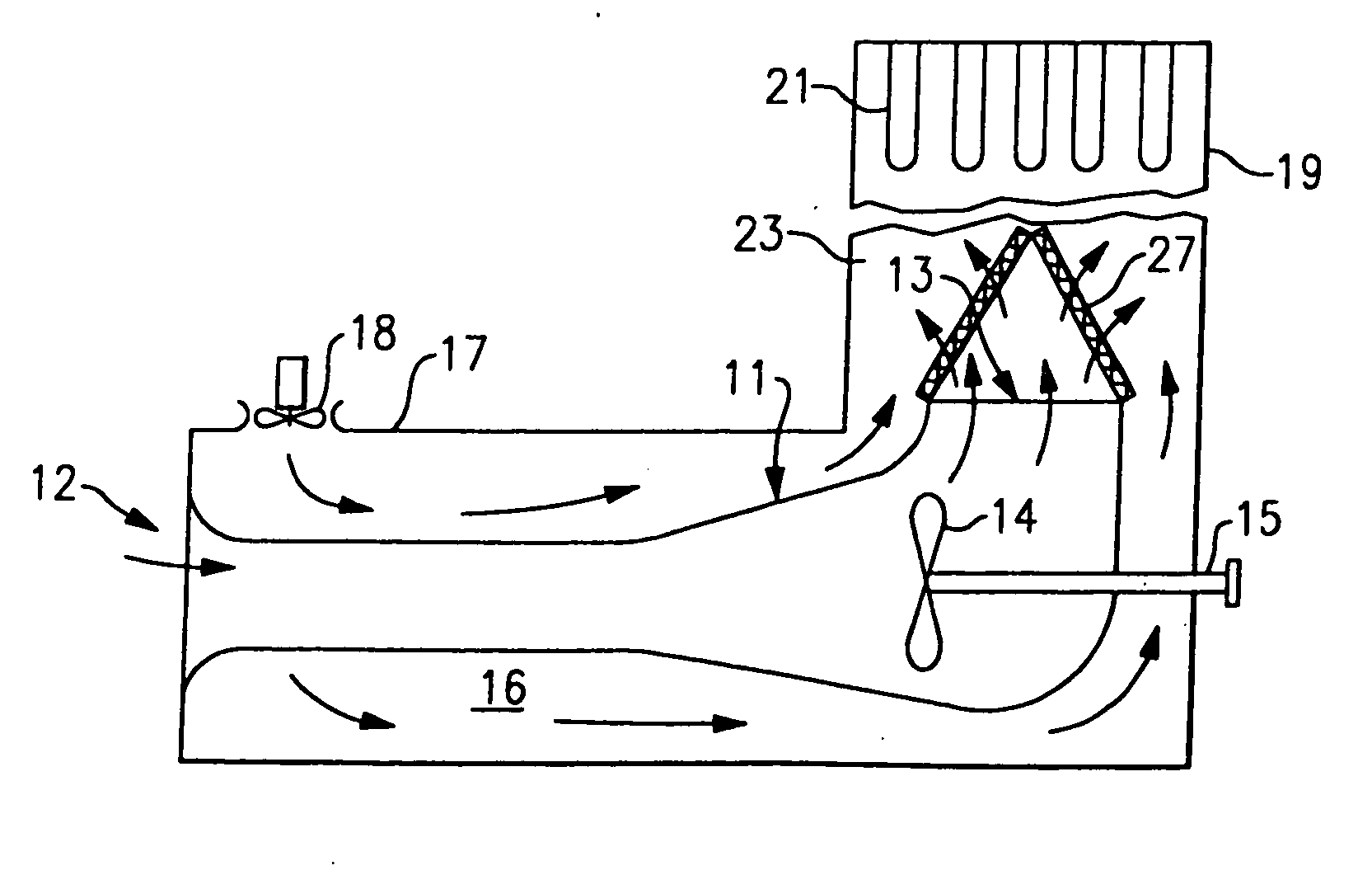
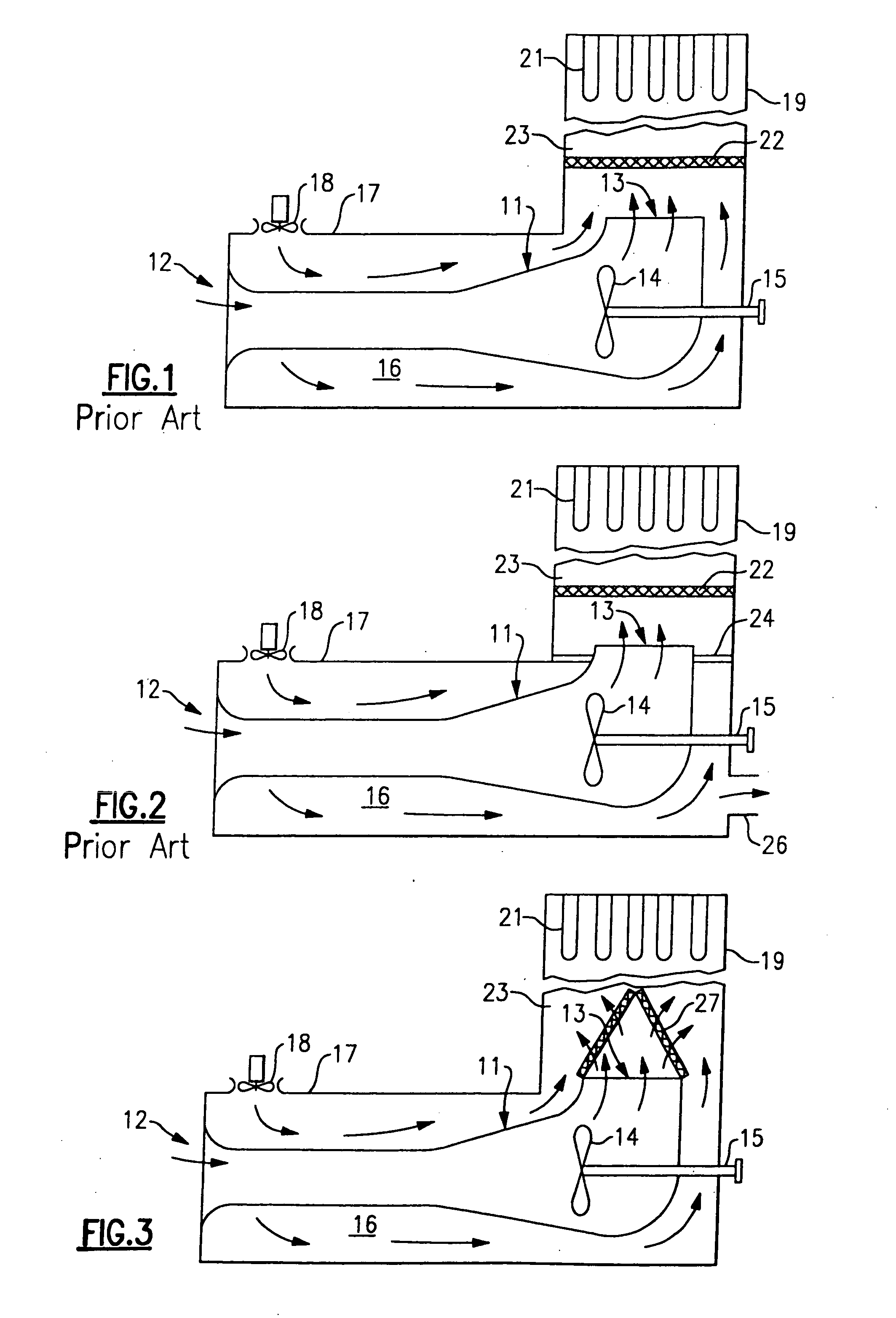
[0011] Referring now to FIG. 1, a gas turbine is shown at 11 having an inlet opening 12 connected to inlet plenum and an exhaust opening 13. In operation, ambient air is admitted to the inlet opening 12 and passes through the turbine 14 to provide motive power thereto, thereby causing rotary motion to the shaft 15. The cooler, lower pressure gases then pass out through the exhaust opening 13.

[0012] Because of the high temperatures within the gas turbine 11, it is desirable to provide a cooling function thereto by way of cooling air which is circulated within an envelope or enclosed space 16 defined by an enclosure 17 surrounding the gas turbine 11. The cooling air is caused to pass through envelope 16 by way of one or more fans 18, with the cooling air then flowing in the direction indicated by the arrows and towards the exhaust opening 13.

[0013] In addition to the function of cooling the gas turbine 11 itself, the cooling air has also been used to cool the exhaust gases, that are...


PUM


Abstract

In a gas turbine installation having an enclosure for passing cooling air therethrough and around the gas turbine, provision is made for a mixing of the cooling air with the exhaust gases being emitted from the gas turbine to thereby reduce the temperature thereof prior to its passing into the exhaust stack, but only after the primary air has passed through a catalyst bed which is disposed in a position over the gas turbine exhaust opening. The shape of the catalyst bed is preferably A-shaped in cross-section to thereby increase the surface area thereof. In this way, the temperature at the catalyst bed is maintained at an elevated level to obtain superior performance while a subsequent mixing of the primary air with the cooling air results in lower temperatures of the gases passing through the exhaust stack.

Description

BACKGROUND OF THE INVENTION [0001] This invention relates generally to gas turbines and, more particularly, to a catalyst bed which is placed in the exhaust stream of a gas turbine. [0002] In an effort to reduce undesirable emissions such as carbon monoxide, it has become common to provide a catalyst bed at the exhaust to reduce the harmful emissions prior to the exhaust gases being passed through the exhaust stack and into the atmosphere. [0003] It has also become customary to provide a flow of cooling air within the enclosure around a gas turbine and to mix the cooling air with the gas turbine exhaust gases so that the temperatures are reduced when passing through the exhaust silencers and the exhaust stack. It has been recognized that if a catalyst bed is introduced in such an arrangement, that both the turbine exhaust gases and the cooling air pass through the catalyst bed, then the pressure drop through the catalyst would cause excessive pressure rise in the enclosure and reduc...

Claims


Application Information

Patent Timeline
IPC IPC(8): F02C7/00
CPCF01D25/26F01D25/30Y02E20/363F23J15/06F23R3/02F23G7/07
Inventor PATEL, ANANT RAMBHAISTAIB, BERNARD G.
Owner M ITSUBISHI POWER AERO LLC
Why Eureka
Try Eureka