
Toe-To-Heel Waterflooding With Progressive Blockage Of The Toe Region

a technology of toe-to-heel waterflooding and toe-to-heel, which is applied in the direction of sealing/packing, drilling pipes, and well accessories, can solve the problems of low injectivity, poor sweep efficiency, and high cost of zonal isolation and blocking of a portion of the reservoir through which water is condensed, so as to increase the ultimate oil recovery and reduce the current water cut

Active Publication Date: 2007-03-29
INNOTECH ALBERTA INC
View PDF41 Cites 16 Cited by
  • Summary
  • Abstract
  • Description
  • Claims
  • Application Information

AI Technical Summary

Benefits of technology

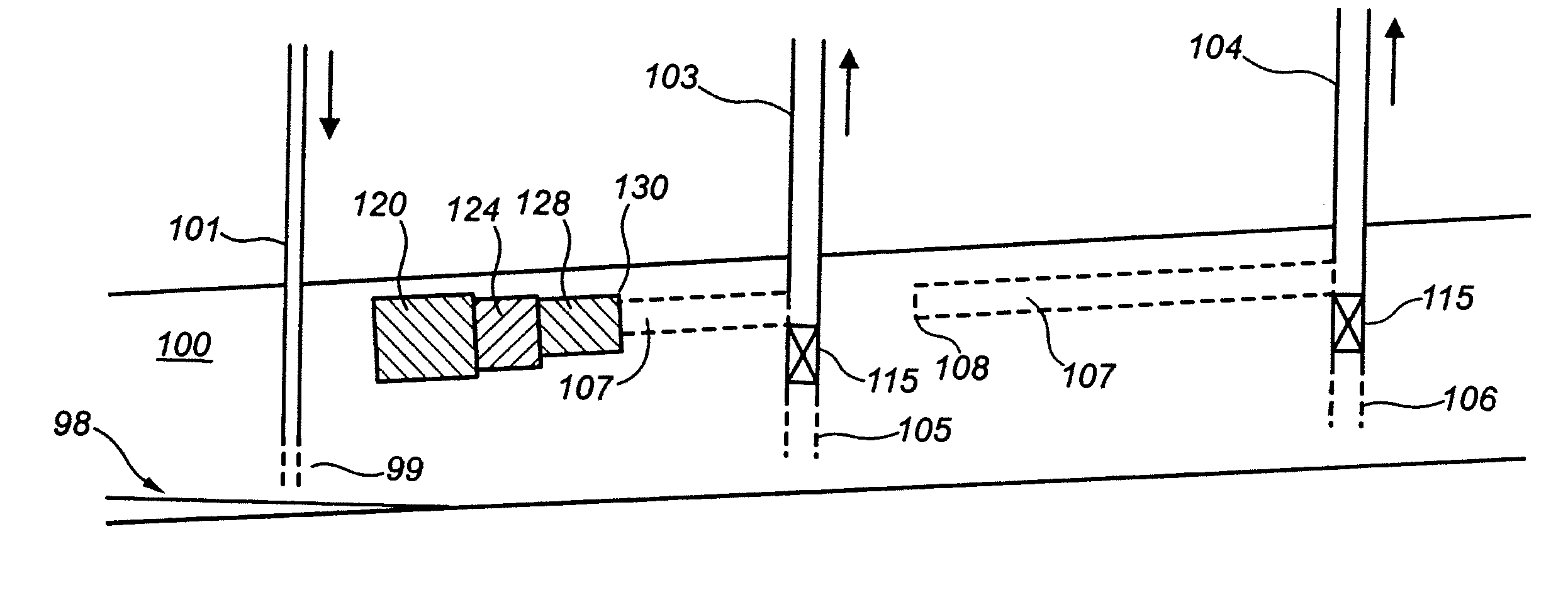
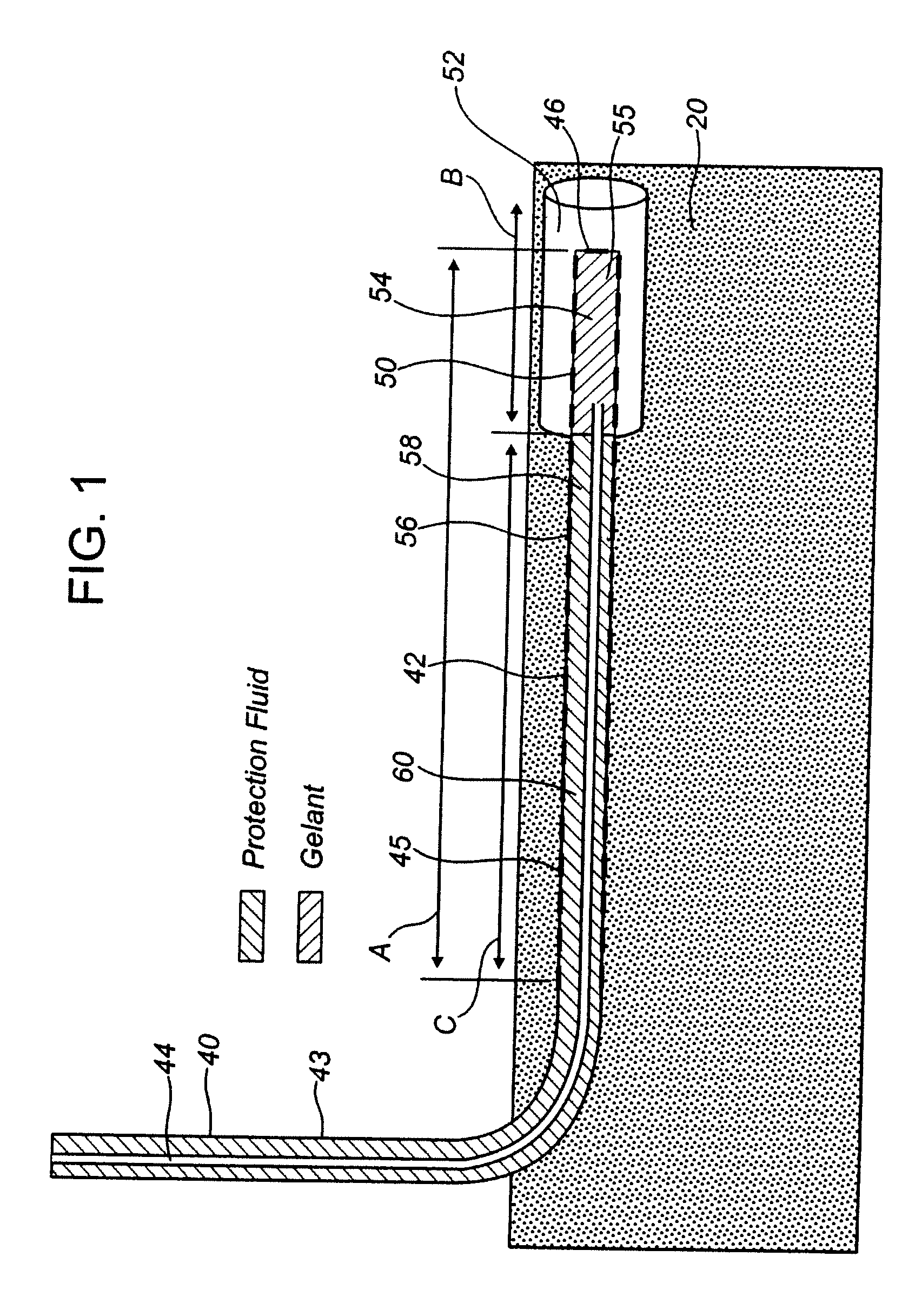
[0007] The improvement in the TTHW oil recovery process provided by this invention includes progressive blockage of the toe region of the horizontal leg of the production well. Increasing and successive portions of the horizontal leg of the production well adjacent to the toe are blocked, such that only the remaining portion of the horizontal leg, closer to the heel, is open for oil production. This progressive blockage of the toe region results in reduced water cuts and improved oil recovery in comparison to the single stage TTHW process described above.
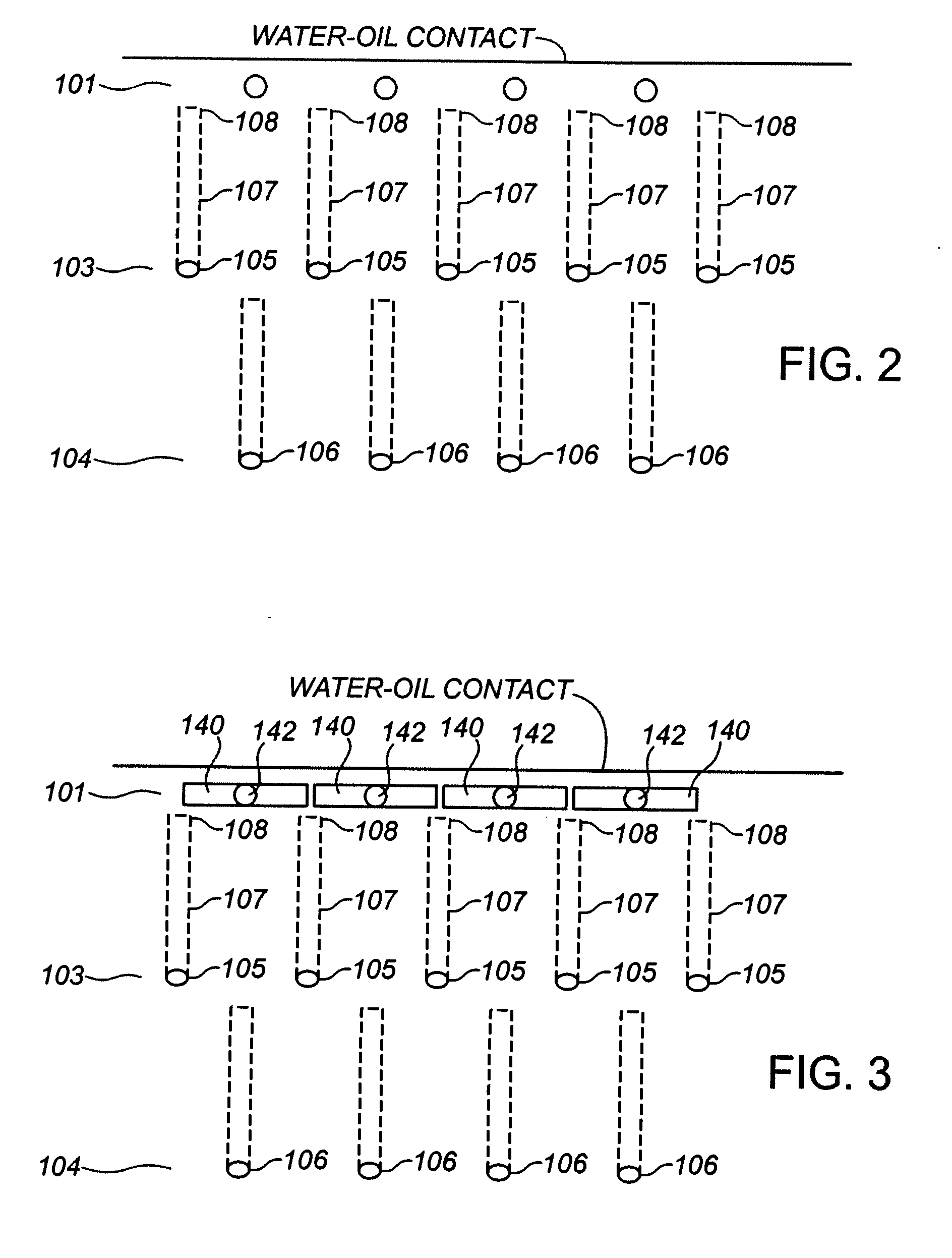
[0013] After a period of production as set forth in step c above, in accordance with the present invention, the TTHW process is modified when the producing toe portion of the horizontal leg of the production well is chemically blocked, and only the remaining portion, heel-adjacent region (termed the new producing toe portion) is left open to oil production. This step of blocking can be repeated as the new producing toe becomes watered out in order to progressively block producing toe portions toward the heel of the production well. This modified process, with a progressive series of blockages is found to result in a decrease in current water cut and an increase of ultimate oil recovery. The process can be repeated until blockage of the horizontal leg has progressed back to the pilot hole of the horizontal well, which is open for production. When the water cut at the pilot hole increases to a high value (say about 90-95%), then the pilot hole well can be converted to a water injection well, the former water injection well can be shut-in; and a new horizontal well located in a next nearest row can be opened for production.
[0031] The process of the present invention has important advantages compared to prior art recovery processes for a similar reservoir, including a decrease in current water cut, an increase of ultimate oil recovery, and the avoidance of having to perform production logging to find the “offending” zone for blocking.

Problems solved by technology

Irrespective of whether premature water break-through in a horizontal well is coming from a coning situation in a reservoir with bottom water, or from a waterflood operation, the zonal isolation and blocking of a portion of the reservoir through which water is coning is a very complex and costly operation which generally involves the following steps or operations.
Conventional waterflooding in heavy oil reservoirs is associated with either very large pressure gradients or premature water break-through, and both these aspects lead to low injectivity or poor sweep efficiency, and result in poor oil recovery.

Method used


Image

  • Toe-To-Heel Waterflooding With Progressive Blockage Of The Toe Region
  • Toe-To-Heel Waterflooding With Progressive Blockage Of The Toe Region
  • Toe-To-Heel Waterflooding With Progressive Blockage Of The Toe Region

Examples


example 1

Test Cell

[0075] The 3D cell depicted schematically in FIG. 5 was used to demonstrate the efficiency of the improved TTHW process when applied with progressive blockage of the toe region. This cell consisted of a rectangular vessel 70 containing a porous medium 72, with two vertical injectors 74, and one horizontal producer 76 laid out in a staggered line drive configuration. The dimensions of the rectangular chamber 70 were: 38.1 cm×38.1 cm×10.8 cm; the total volume was 15.7 liters, while the pore volume was approx. 5.6 liters, at a porosity estimated at 36%.

[0076] The horizontal producer 76 was located 3 cm from the top and was perforated 24 cm. Its toe 78 was located 8 cm from the line of vertical injectors 74, which were perforated on 5.8 cm at the lower part of layer.

[0077] The horizontal producer 76 had an inside diameter of 0.120″ (3.75 mm), with a cross sectional area of 0.07917 cm2 (7.917 mm2 ). The vertical injectors 74 had the same inside diameter. All wells are perfora...

example 2

Simulations

[0106] The improvement of the performance of TTHW process by progressive blockage of the toe region was confirmed by numerical simulation studies using discretized wellbore in a commercial simulation package. For the study of the reservoir behaviour, the wellbore was treated as an ensemble of segments or grid blocks, and the reservoir flow equations are coupled with the ensuing flow inside each of these segments.

[0107] The discretized wellbore model is a fully coupled mechanistic wellbore model. It models the fluid flow between the wellbore and the reservoir. The wellbore mass conservation equations are solved together with reservoir equations for each wellbore segment. Two correlations are used to calculate the friction pressure drop and liquid holdup gas-liquid in the wellbore. Bankoff's correlation is used to evaluate the liquid holdup and Duckler's correlation is used to calculate the friction pressure drop. The oil-water mixture is considered as a homogeneous liqui...


PUM


Abstract

A modified toe-to-heel waterflooding (TTHW) process is provided for recovering oil from a reservoir in an underground formation. After establishing the conventional TTHW waterflood, the process includes placing a chemical blocking agent at the watered out producing toe portion of the horizontal leg of the production well to create a blockage in the producing toe portion and to create a new producing toe portion in an open portion of the horizontal leg adjacent the blockage through which most of the production takes place. Production is then continued through the new producing toe portion and the open portion of the horizontal leg of the production well. These blocking and producing steps can be continued to progressively block producing toe portions in a direction toward the vertical pilot portion of the production well.

Description

CROSS REFERENCE TO RELATED APPLICATIONS [0001] This application is a Continuation of International Application No. PCT / CA2006 / 000327, filed Mar. 9, 2006, which claims priority from U.S. Provisional Patent Application No. 60 / 719,901, filed Sep. 23, 2005. FIELD OF THE INVENTION [0002] The invention relates to an improved Toe-to-Heel Waterflooding (TTHW) process for the recovery of oil from an underground oil reservoir. BACKGROUND OF THE INVENTION [0003] The Toe to Heel Waterflooding (TTHW) process is described in U.S. Pat. No. 6,167,966, issued Jan. 2, 2001 to the same assignee as the present case. Briefly, the TTHW consists of guiding the advance of a liquid displacement front originating from an injection well by having a production well with an open horizontal leg oriented towards the injection well act as a linear pressure sink to which the front is attracted and by which the front is guided. The present invention is directed to the problem of watering out or coning associated wit...

Claims


Application Information

Patent Timeline
Patent Type & Authority Applications(United States)
IPC IPC(8): E21B43/30E21B43/16
CPCE21B43/20E21B43/32E21B43/305
Inventor TURTA, ALEXWASSMUTH, FREDSHRIVASTAVA, VIJAYSINGHAL, ASHOK
Owner INNOTECH ALBERTA INC
Learn More