Electrically powered steering apparatus

a technology of electric steering and steering shaft, which is applied in the direction of apparatus for force/torque/work measurement, instruments, transportation and packaging, etc., can solve the problems of high resistance of magnetostrictive plating materials and carbon components diffused in the surface of the torque transmission shaft, so as to enhance workability, and increase the stability of magnetostrictive properties

Inactive Publication Date: 2007-03-29
HONDA MOTOR CO LTD
View PDF21 Cites 48 Cited by
  • Summary
  • Abstract
  • Description
  • Claims
  • Application Information

AI Technical Summary

Benefits of technology

[0017] In this way, both the magnetostrictive film and the pinion can be formed on the torque transmission shaft by processes appropriate for each, so workability is enhanced. The stability of the magnetostrictive properties of the magnetostrictive film can be increased as well. By increasing the stability of magnetostrictive properties, sensor signals from the magnetostrictive torque sensor can be stabilized to a sufficient extent, and sensor accuracy increased.
[0018] As a result, for example, in an electrically powered steering apparatus wherein the steered wheels are steered by the combined torque of the steering torque from the driver and the assisting torque from an electrical motor, the steering torque transmitted to the torque-side shaft can be sensed with consistently good accuracy by the magnetostrictive torque sensor. Consequently, the steering feel of the steering wheel or other steering component can be sufficiently enhanced.

Problems solved by technology

However, subjecting a pinion to a heat treatment results in carbon components being diffused in the surface of the torque transmission shaft that has the pinion.
Such magnetostrictive plating materials are highly susceptible to the effects of magnetism from the torque transmission shaft and the effects of strain in the torque transmission shaft.

Method used


Image

  • Electrically powered steering apparatus
  • Electrically powered steering apparatus
  • Electrically powered steering apparatus

Examples


Embodiment Construction

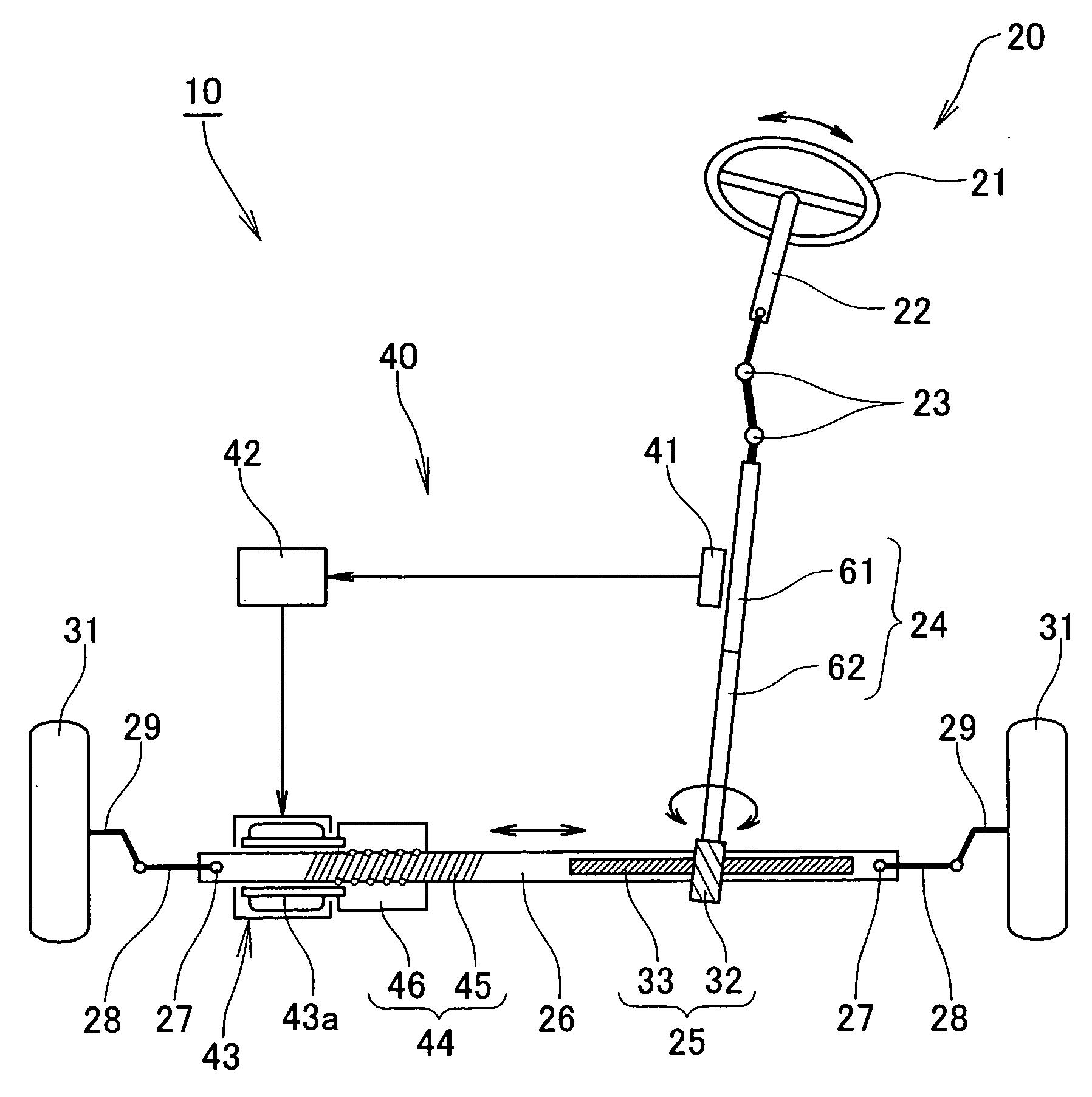
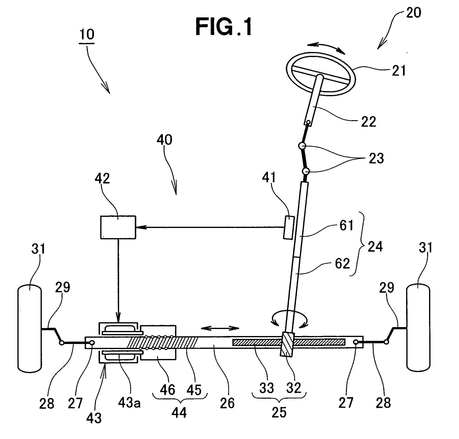
[0037] Reference is now made to FIGS. 1 to 5 inclusive, which illustrate an embodiment of the electrically powered steering apparatus. As shown in FIG. 1, the electrically powered steering apparatus 10 comprises a steering system 20 extending from the steering member 22 of the vehicle to steered wheels 31, 31 of the vehicle; and a torque assist mechanism 40 for providing an assist torque to the steering system 20.

[0038] The steering member 21 comprises a steering wheel, for example (hereinafter the steering member 21 shall be termed “steering wheel 21” where appropriate). The steered wheels 31, 31 are the left and right front wheels, for example.

[0039] The steering system 20 comprises the steering wheel 21; a torque transmission shaft 24 linked to the steering wheel 21 via a steering shaft 22 and swivel joints 23, 23; a rack shaft 26 linked to the torque transmission shaft 24 via a rack-and-pinion mechanism 25; and the left and right steered wheels 31, 31, which are linked to the ...


PUM

PropertyMeasurementUnit
thicknessaaaaaaaaaa
torqueaaaaaaaaaa
magnetostrictiveaaaaaaaaaa

Abstract

An electrically powered steering apparatus in which at least one torque selected from a steering torque and a motor torque is transmitted from a torque transmission shaft to a rack-and-pinion mechanism to steer steered wheels. The torque transmission shaft has a torque-side shaft provided with a magnetostrictive film of a magnetostrictive sensor for sensing torque; and a pinion shaft provided with a pinion of the rack-and-pinion mechanism. The torque-side shaft and the pinion shaft are separate components which are linked together.

Description

FIELD OF THE INVENTION [0001] The present invention relates to an electrically powered steering apparatus that employs a so-called rack-and-pinion mechanism and is designed to steer the steered wheels of a vehicle by transmitting a motor torque or a steering torque that corresponds to steering to a rack shaft via a rack-and-pinion mechanism. BACKGROUND OF THE INVENTION [0002] In recent years, electrically powered steering apparatuses that employ a rack-and-pinion mechanism have come to be widely used in order to reduce the steering force of the steering wheel and provide a pleasant steering response. This kind of electrically powered steering apparatus is designed to transmit both a steering torque and a motor torque, or a steering torque only, to the rack shaft via a torque transmission shaft and a rack-and-pinion mechanism. [0003] The steering torque and the motor torque are sensed by a torque sensor provided to the torque transmission shaft. Magnetostrictive torque sensors, which...

Claims


Application Information

Patent Timeline
Patent Type & Authority Applications(United States)
IPC IPC(8): B62D5/04
CPCB62D3/12B62D6/10Y10T29/49002G01L5/221G01L3/103G01L3/102
Inventor SHIMIZU, YASUO
Owner HONDA MOTOR CO LTD
Why Eureka
Try Eureka