
Absolute linear encoder

an encoder and absolute technology, applied in the field of absolute linear encoders, can solve the problems of difficult manufacturing of integral absolute scales, difficult to manufacture integral long scales, and difficult to manufacture integral absolute scales over long time scales, etc., and achieves low cost, easy transportation and attachment, and long measurement range.

Active Publication Date: 2007-03-29
MITUTOYO CORP
View PDF5 Cites 19 Cited by
  • Summary
  • Abstract
  • Description
  • Claims
  • Application Information

AI Technical Summary

Benefits of technology

[0009] The present invention has been devised to solve the foregoing conventional problems. An object of the present invention is to provide a long absolute linear encoder which covers a long measurement range and is easy to transport and attach at low costs.
[0020] According to the present invention, since division can shorten scale length with respect to final measuring range of absolute scale (for example, two 3 m scales for 6 m measuring range), manufacturing equipment for a long scale is unnecessary and it is possible to easily manufacture the scale at low costs. There are transport cost and storage cost advantages too.
[0021] Furthermore, an integral scale is difficult to not only transport and store but also attach. In the case of the divided scale, however, attachment can be easily carried out on a short scale basis.

Problems solved by technology

However, in the case of, for example, a photoelectric scale, there are limitations on the length of an exposure device for forming calibrations on the scale, so that it is difficult to manufacture the integral long scale.
In the case of the absolute scale for detecting the absolute position, however, manufacturing a long integral absolute scale over, for example, 3 m is not easy.
Even if a long scale can be manufactured, there is a problem that the integral scale is not easy to transport and attach.

Method used


Image

  • Absolute linear encoder
  • Absolute linear encoder
  • Absolute linear encoder

Examples


Embodiment Construction

[0035] Exemplary embodiments of the present invention will be hereinafter described in detail with reference to drawings.

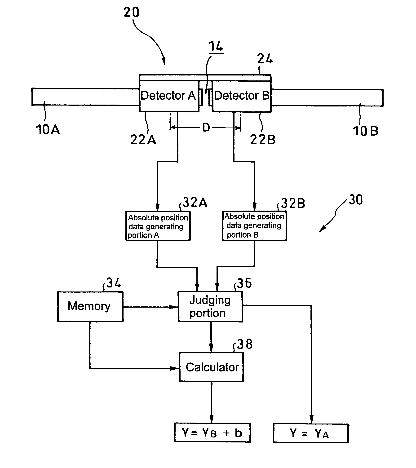
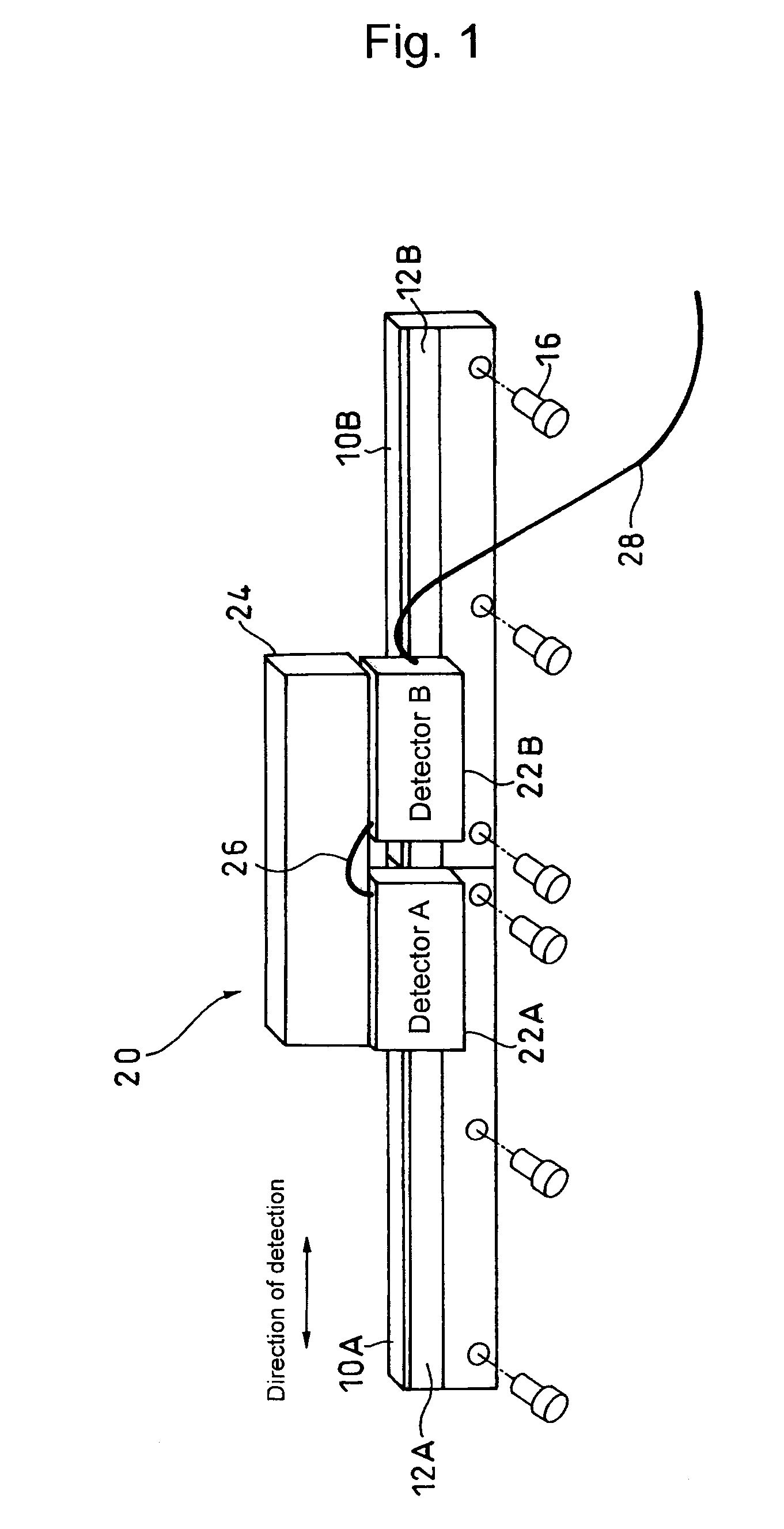
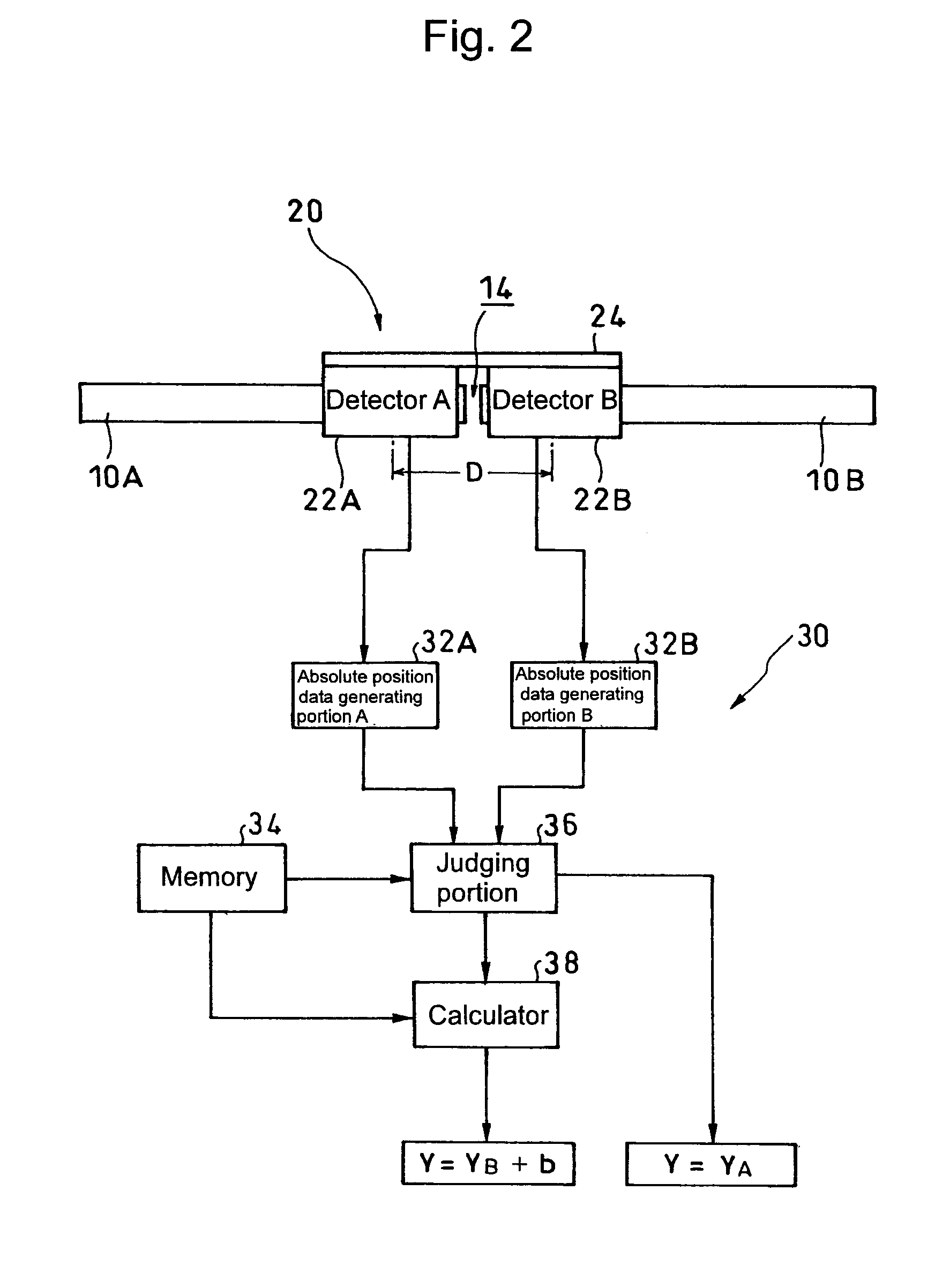
[0036] A first exemplary embodiment of the present invention in which two absolute scales are connected comprises, as shown in FIG. 1 (perspective view of essential structure) and FIG. 2 (block diagram of a signal processing circuit), two absolute scales (hereinafter simply called “scale” too) 10A and 10B, a detection head 20, and a signal processing circuit 30.

[0037] The two absolute scales 10A and 10B aligned in the direction of detection (horizontal direction in the drawing) have different absolute calibrations (hereinafter simply called “calibrations” too) 12A and 12B to detect an absolute position.

[0038] The detection head 20 has detectors 22A and 22B for detecting the calibrations 12A and 12B on the absolute scales 10A and 10B. The detectors 22A and 22B are fixed by a coupling board (may be a bracket of a user) 24 at such an arbitrary central interval D a...


PUM


Abstract

An absolute linear encoder includes a plurality of absolute scales aligned in the detection direction with absolute calibrations, a plurality of detectors for detecting the calibrations on the absolute scales, absolute position data generating portions of each scale for generating absolute position data of each detector, and a calculator for outputting an absolute position over the whole length of connected whole absolute scales adding the absolute position data of each detector and the distance between the detectors. The detectors are fixed at such intervals as to simultaneously detect the calibrations of the two absolute scales adjoining in a scale connecting section. Thus, the long absolute linear encoder which is easy to use is realized at low costs.

Description

CROSS-REFERENCE TO RELATED APPLICATION [0001] The disclosure of Japanese Patent Application No. 2005-283625 filed on Sep. 29, 2005 including specifications, drawings and claims is incorporated herein by reference in its entirety. BACKGROUND OF THE INVENTION [0002] 1. Field of the Invention [0003] The present invention relates to absolute linear encoders for detecting an absolute position. In particular, the present invention relates to an absolute linear encoder which covers a long measurement range and is easy to handle. [0004] 2. Description of the Related Art [0005] In order to enable a linear scale to cover a long measurement range, it is necessary to manufacture a long scale. However, in the case of, for example, a photoelectric scale, there are limitations on the length of an exposure device for forming calibrations on the scale, so that it is difficult to manufacture the integral long scale. [0006] Thus, in an incremental scale in which a calibration pattern for detecting rel...

Claims


Application Information

Patent Timeline
Patent Type & Authority Applications(United States)
IPC IPC(8): G01D5/34
CPCG01D3/024G01D5/34776G01D5/2497G01D5/34753
Inventor SAKAGAMI, SEIJITERAGUCHI, MIKIYA
Owner MITUTOYO CORP
Learn More