
Rider separation detecting device

a technology of detecting device and rider, which is applied in the direction of nuclear elements, cycle equipment, tractors, etc., can solve the problems of affecting the behavior of the rider, affecting the detection effect, and affecting the performance of the rider, so as to achieve the separation of the rider and the rider precisely and quickly, and achieve good external appearance

Inactive Publication Date: 2007-03-29
HONDA MOTOR CO LTD
View PDF20 Cites 17 Cited by
  • Summary
  • Abstract
  • Description
  • Claims
  • Application Information

AI Technical Summary

Benefits of technology

[0007] It is accordingly an object of the present invention to provide a rider separation detecting device which can precisely and quickly detect the separation of a rider from a rider's seat without improper detection and can ensure a good external appearance without hindering a normal action of the rider on the rider's seat.
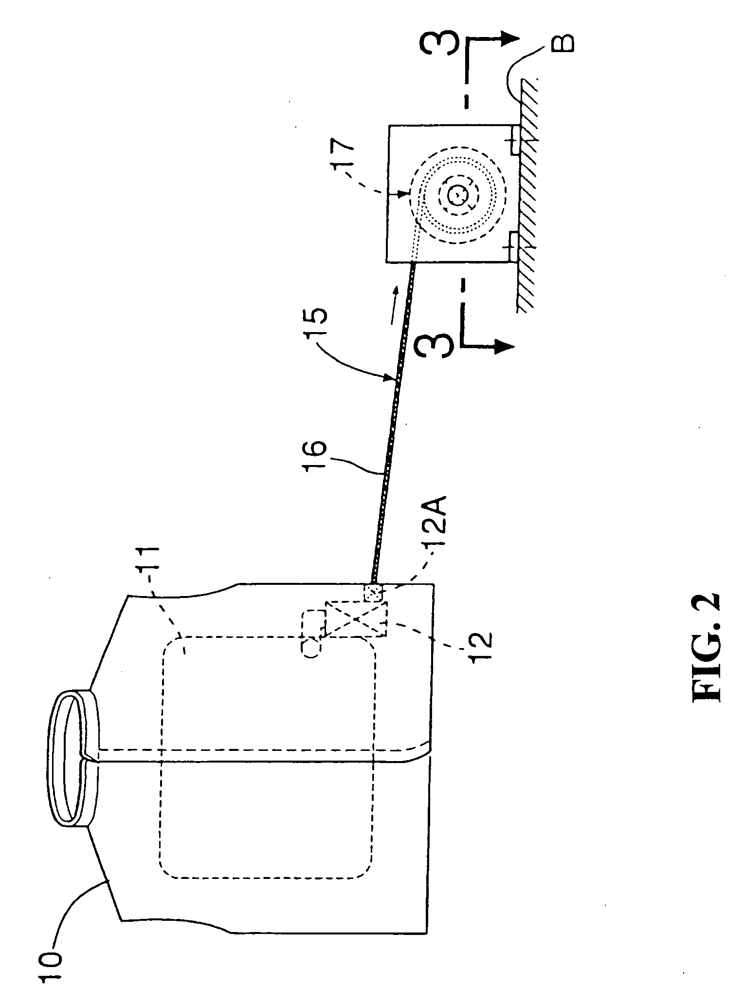
[0012] According to the first aspect of the invention, when the rider separates from the rider's seat to unwind the cable, the drum is therefore rotated by the cable and the rotational angle of the drum at that time is detected by the rotational angle detecting means. Then, the separation of the rider from the rider's seat is determined by the separation determining means according to a detection value from the rotational angle detecting means. Accordingly, the separation of the rider from the rider's seat can be detected precisely and quickly without improper detection due to forgetting to remove the cable. Further, slacking of the cable can be prevented to ensure a good external appearance and not to hinder the behavior of the rider on the rider's seat.
[0013] According to the second aspect of the invention, the separation determining means determines the separation of the rider according to the unwinding length, the unwinding velocity, and the unwinding acceleration of the cable, or according to a relative displacement, a relative displacement velocity, and a relative displacement acceleration between the rider and the vehicle. Accordingly, the separation of the rider from the rider's seat can be detected more precisely.

Problems solved by technology

While this detection method is simple, there is a possibility that when the rider forgets to remove the cable and moves in a small amount, the detecting portion may be separated improperly.
If the length of the cable is set sufficient to avoid the above possibility, the cable becomes a slack condition, causing a degradation in external appearance and a possibility of hindrance to the behavior of the rider.

Method used


Image

  • Rider separation detecting device
  • Rider separation detecting device
  • Rider separation detecting device

Examples


Embodiment Construction

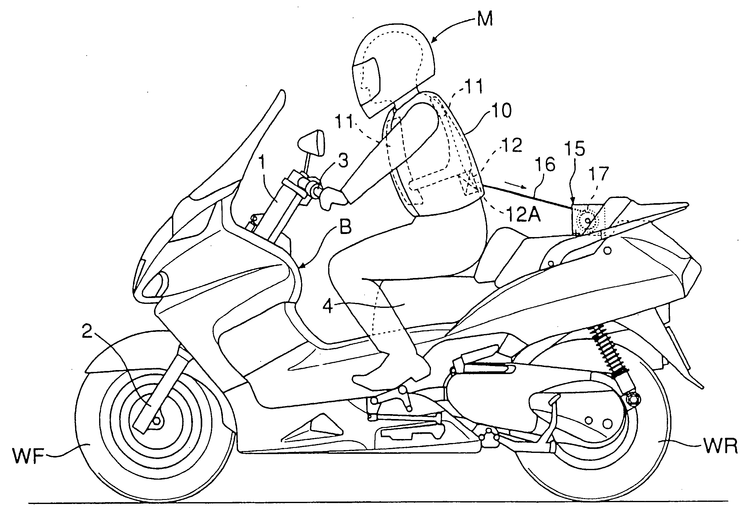
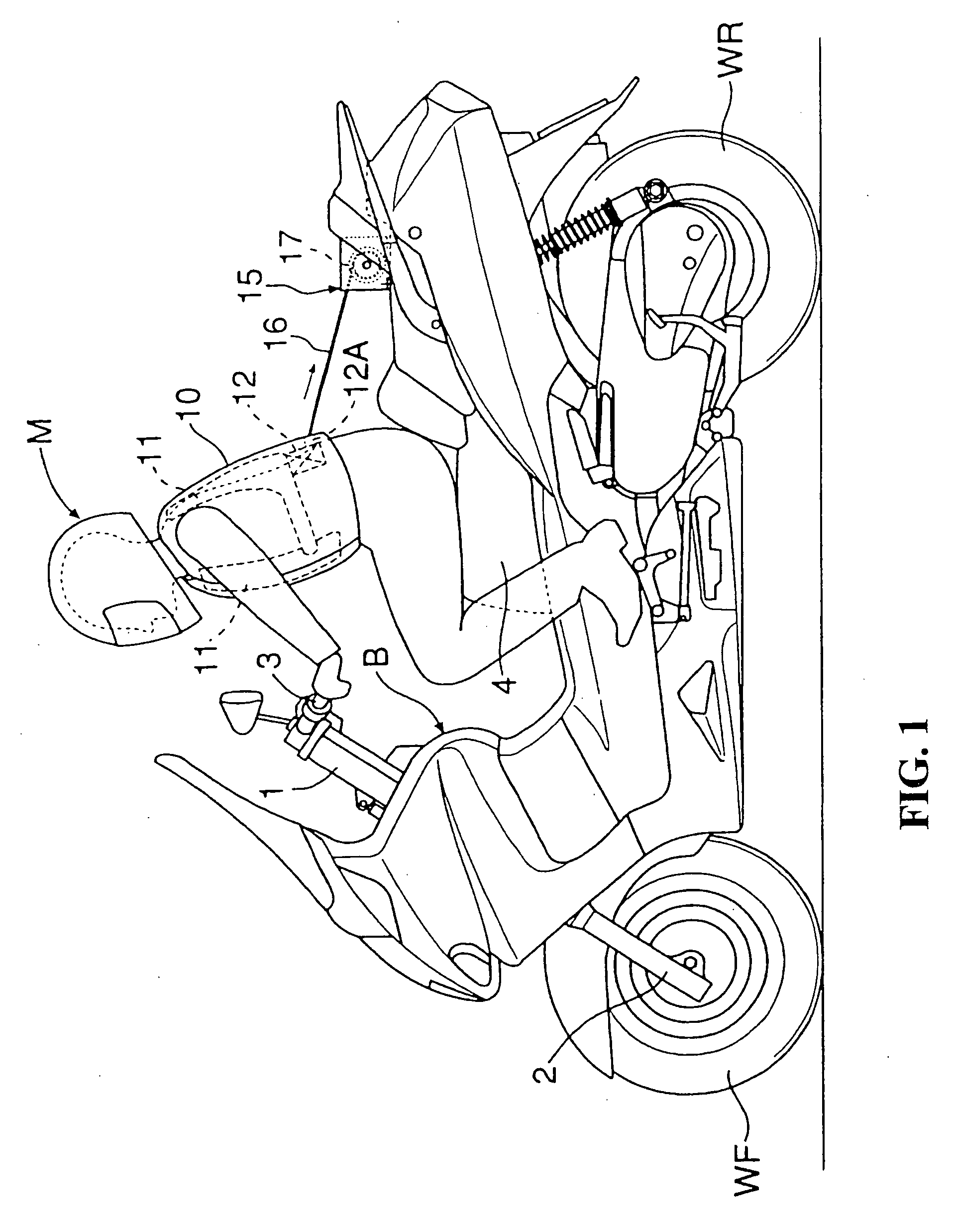
[0023] Referring first to FIG. 1, the motorcycle has a vehicle body B, and a head pipe 1 is provided at the front end of the vehicle body B. A front fork 2 is steerably supported to the head pipe 1, and a front wheel WF is rotatably supported through its axle to the front fork 2. A steering handle 3 is connected to an upper portion of the front fork 2. An engine is mounted on the vehicle body B, and a rear wheel WR to be driven by the engine is supported to a rear portion of the vehicle body B. A rider's seat 4 is provided on an upper surface of the vehicle body B at a longitudinally intermediate portion thereof.

[0024] Referring also to FIG. 2, a garment 10 such as a vest is preliminarily worn by a rider M, and the rider M thus wearing the garment 10 sits on the rider's seat 4. The garment 10 includes an air bag 11 adapted to be inflated to project from the outer surface of the garment 10, thereby covering the front and back sides of the upper body of the rider M. The garment 10 fu...


PUM


Abstract

A rider separation detecting device for precisely and quickly detecting the separation of a rider from a rider's seat. The rider separation detecting device includes a cable connected at one end thereof to one of a garment worn by the rider and a vehicle body, and winding mechanism having a drum connected to the other end of the cable and rotationally biased in a direction of winding of the cable. The winding mechanism is provided on the other of the garment and the vehicle body. Also included are a rotational angle detecting mechanism for detecting a rotational angle of the winding mechanism, and separation determining mechanism for determining the separation of the rider from the rider's seat according to a detection value from the rotational angle detecting mechanism. The device ensures proper detection and a good external appearance without hindering a normal action of the rider on the rider's seat.

Description

CROSS-REFERENCE TO RELATED APPLICATION [0001] The present application claims priority under 35 U.S.C. §119 to Japanese Patent Application No. 2005-266693, filed Sep. 14, 2005, the entire contents of which are hereby incorporated by reference. BACKGROUND OF THE INVENTION [0002] 1. Field of the Invention [0003] The present invention relates to a rider separation detecting device for detecting the separation of a rider from a rider's seat of a vehicle. [0004] 2. Description of Background Art [0005] Conventionally known from Japanese Utility Model Registration No. 3048094 and Japanese Utility Model Registration No. 3063889 is an air bag system wherein when a rider sitting on a rider's seat of a motorcycle separates from the rider's seat in the event of a collision or the like, a cable connected at one end thereof to the rider is pulled, thereby releasing a key provided at the other end of the cable and inflating an air bag. [0006] In the air bag system disclosed in Japanese Utility Mode...

Claims


Application Information

Patent Timeline
IPC IPC(8): B60R21/18B62J99/00
CPCA41D13/018A41D2600/102B62J27/00B60R2021/0088B60R21/015B62J27/20
Inventor KOBAYASHI, YUKIGOTO, HIROSHINAGATSUYU, TOSHIYA
Owner HONDA MOTOR CO LTD
Learn More