Battery charger and power reduction system and method

a battery charger and power reduction technology, applied in the field of batteries chargers and power reduction systems and methods, can solve the problems of rapid chargers that may overcharge, inconvenient charging, and battery damage, and achieve the effects of reducing costs, effective charging batteries, and minimizing the amount of power needed

Active Publication Date: 2007-03-29
U S GOVT AS REPRESENTED BY THE DEPT OF THE NAVY
View PDF37 Cites 15 Cited by
  • Summary
  • Abstract
  • Description
  • Claims
  • Application Information

AI Technical Summary

Benefits of technology

[0011] A feature of the present invention is that it uses a common charging source and shunt style charging circuits to regulate the charging process, which may provide the advantage of allowing the battery charger to effectively charge batteries at a lower cost.
[0012] Through the present invention's use of hardware and software, another feature of the present invention is that it possibly minimizes the amount of power needed for charging purposes. This possibly provides the following advantages: an increase in efficiency; a reduction in the likelihood of overcharging conditions; and a reduction in the generation of heat.
[0013] Another advantage of lower power use (and the consequent generation of heat) is the possible elimination of the need for supplemental cooling, which possibly provides an additional advantage of being capable of lower manufacturing costs, e.g., lower production costs, and may decrease the deleterious effects that such heat may have on the battery charger (e.g., its component parts).
[0014] Still another feature of the battery charger is that it may use readily available components; however, it is not limited to these components. An advantage of this is that the battery charger could have the flexibility to be configured for standard sizes / shapes (and for standard full-charge voltage-levels), or it could be easily configured to meet other standards and / or requirements (and / or to use other components as they are developed).
[0015] It is a further feature of the present invention to be functionally and operationally simple to use, yet be highly durable and reliable.

Problems solved by technology

While many of these chargers are generally adequate, charging problems may still arise due to various design constraints.
As examples, the low charge-rate charger may take an inconvenient amount of time to complete its task; the timed charger may complete its “timed charging cycle” before the batteries that are being charged are actually fully charged; and the rapid charger may overcharge and possibly ruin a battery.
Regarding this, and as an example, rechargeable lithium-ion batteries are intolerant to overcharge conditions, and may experience early cycle life failures.
This overcharging problem is heightened in applications that are configured to charge multiple series-connected batteries from a common charging source.
In such configurations, some of the batteries being charged may become fully charged earlier then others, which may subject these batteries to an overcharge condition that could shorten their cycle life.
On the other hand, however, they are very inefficient in operation because of the large amounts of power that they dissipate during the shunting action.
Moreover, while shunt regulators are usually designed to dissipate full power for extended periods-of-time, the use of these higher power levels may shorten the lifetime of any associated electronic circuitry and may require the addition of some form of supplemental cooling.

Method used


Image

  • Battery charger and power reduction system and method
  • Battery charger and power reduction system and method
  • Battery charger and power reduction system and method

Examples


Embodiment Construction

[0025] The devices, circuits, and / or other components described below preferably come from a group of devices, circuits, and / or other components that are well known and / or are commonly available to (or may be fabricated using commonly available knowledge, methods, and / or technology in) the field(s) of electronics or electrical equipment design, and / or to other related fields. And, while the use of these may be preferable, other means of implementing the present invention may also be used as well.

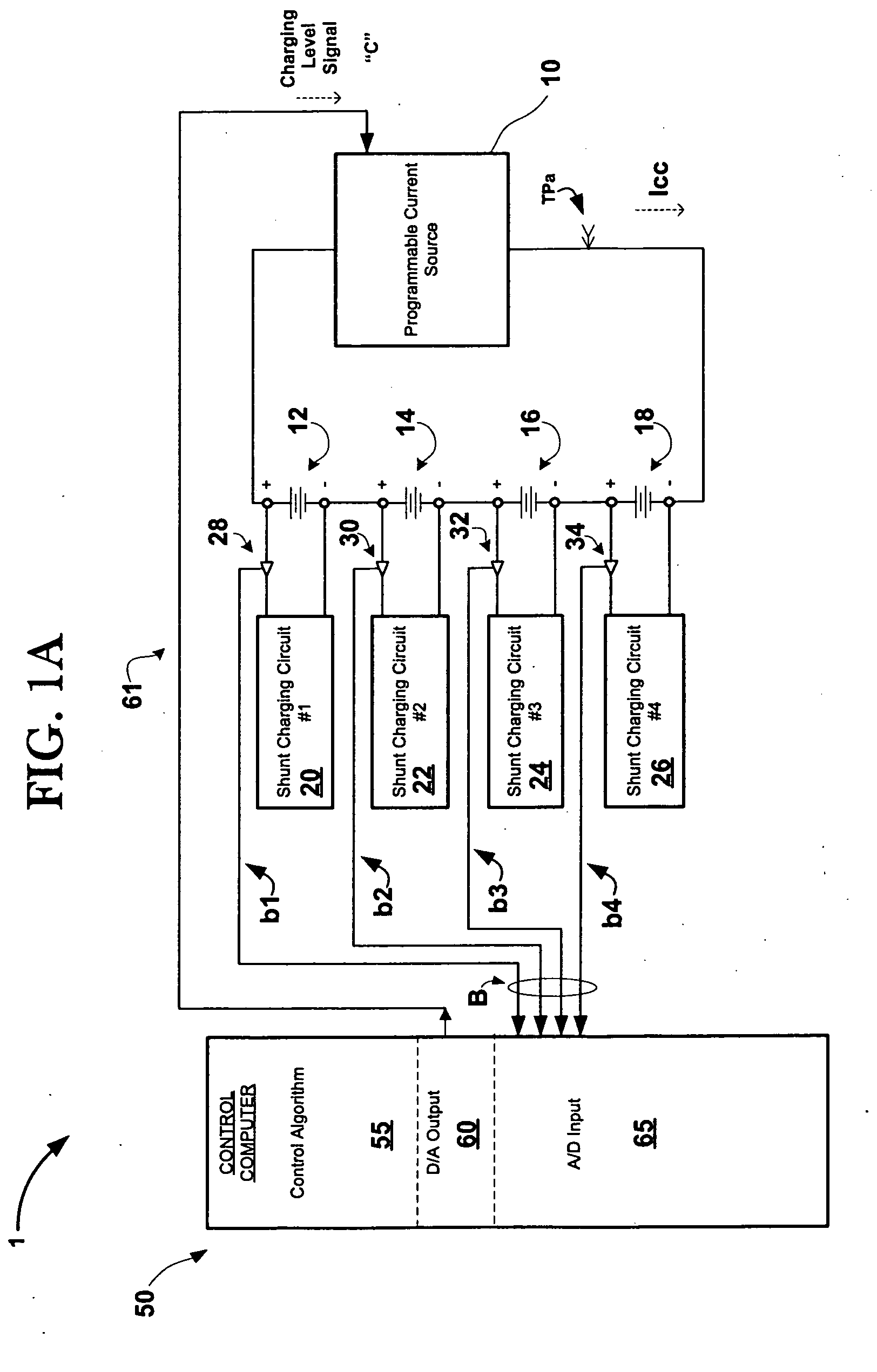
[0026] Referring now to FIG. 1A, a schematic block diagram of an embodiment of the present invention Battery Charger (BC) 1 is shown. As shown, a Programmable Current Source 10 is electrically connected across, and is representationally being used to charge four batteries, which have been removably inserted into battery charging slots 12, 14, 16 and 18. Each battery charging slot 12, 14, 16 and 18 is a part of an associated Shunt Charging Circuit, and, as shown, charging slot 12 is associat...


PUM


Abstract

The present invention is a shunt-type, battery-charging device that (through the use of a power dissipation and/or power reduction system and/or method) is designed to reduce the likelihood of overcharging and the possible deleterious effects (and cooling requirements) associated with the generation of heat during the charging process. Generally, the power reduction system and/or method may control the amount of power being used by the battery charger by monitoring the batteries' level of charge during charging, and by correspondingly reducing the magnitude of the charging current in response to such monitored level.

Description

[0001] The invention described herein may be manufactured and used by or for the Government of the United States of America for governmental purposes without payment of any royalties thereon or therefor.CROSS REFERENCE TO RELATED APPLICATIONS [0002] Not Applicable. STATEMENT REGARDING FEDERALLY SPONSORED RESEARCH OR DEVELOPMENT: STATEMENT REGARDING FEDERALLY SPONSORED RESEARCH OR DEVELOPMENT REFERENCE TO A SEQUENCE LISTING, A TABLE, OR A COMPUTER PROGRAM LISTING COMPACT DISK APPENDIX [0003] Not Applicable. BACKGROUND OF THE INVENTION [0004] The present invention generally relates to an apparatus, and system and / or method capable of charging (or recharging) batteries, and more particularly, but without limitation, to an apparatus, and system and / or method that may be capable of minimizing its power dissipation requirements by adjusting the magnitude of the charging current being sent to the batteries being charged—based, in part, on each battery's level of charge. [0005] Generally, r...

Claims


Application Information

Patent Timeline
Patent Type & Authority Applications(United States)
IPC IPC(8): H02J7/00
CPCH02J7/0016
Inventor HAND, EVAN C.
Owner U S GOVT AS REPRESENTED BY THE DEPT OF THE NAVY
Why Eureka
Try Eureka