

Delay locked loop circuit
- Summary
- Abstract
- Description
- Claims
- Application Information
AI Technical Summary
Benefits of technology
Problems solved by technology
Method used
Image

Examples
first embodiment
[0053]FIG. 5 is a block diagram of the source clock generation unit 300 shown in FIG. 4 in accordance with the present invention; and FIGS. 6A and 6B are detailed circuit diagrams of a second clock divider shown in FIG. 5.
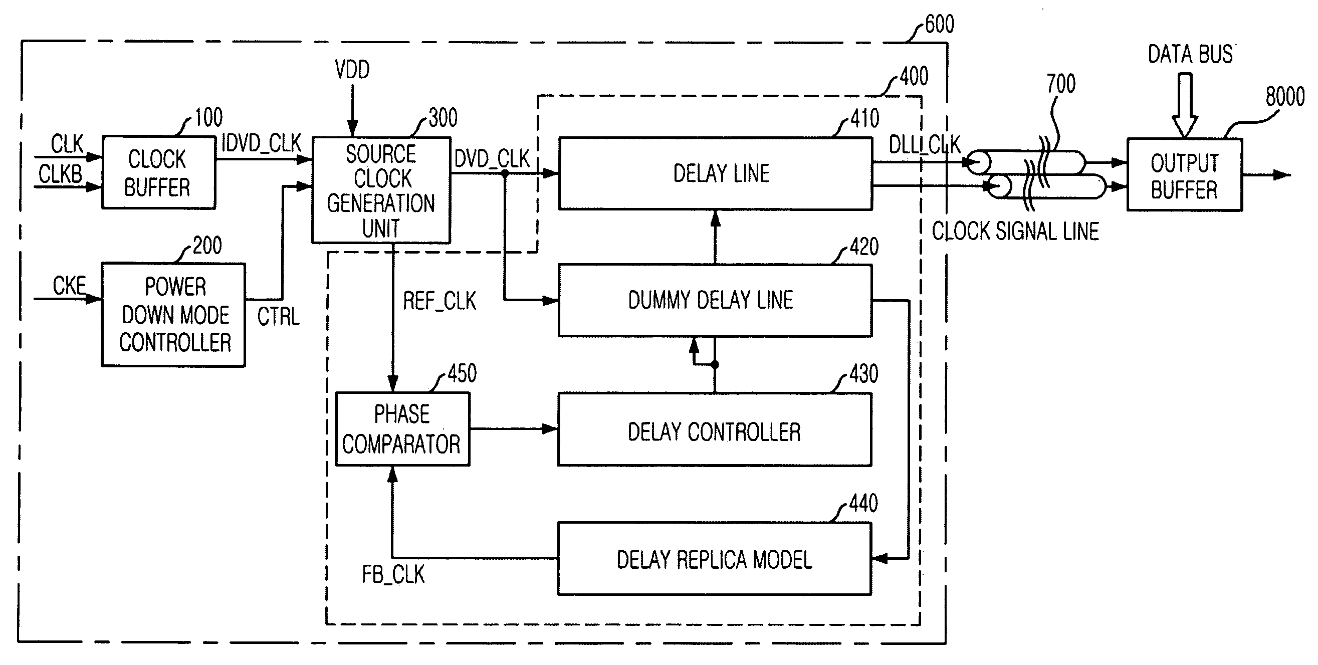
[0054] As shown, the source clock generation unit 300 in accordance with the first embodiment of the present invention includes first and second clock dividers 310 and 320, a selection unit 330, an operational logic unit 340, and a reference clock generation unit 350.
[0055] The first clock divider 310 generates a first division clock signal CLK_D1 to set a duration of the phase update operation in the normal mode by dividing the internal clock signal IDVD_CLK.
[0056] The second clock divider 320 generates a second division clock signal CLK_D2 to set a duration of the phase update operation in the power down mode by dividing the first division clock signal CLK_D1.
[0057] The selection unit 330 selects one of the first and second division clock signals CLK_D1 and CL...
second embodiment
[0076]FIG. 10 is a block diagram showing the source clock generation unit shown 300 in FIG. 4 in accordance with the present invention; and FIGS. 11A and 11B are detailed circuit diagrams of a clock conversion unit of the source clock generation unit 300 shown in FIG. 10.
[0077] Referring to FIG. 10, the source clock generation unit 300 in accordance with the second embodiment of the present invention includes a selection unit 330, an operational logic unit 340, a reference clock generation unit 350, a clock conversion unit 360 and a clock divider 370.
[0078] The clock divider 370 generates a first conversion clock signal CLK_T1 to set a duration of the phase update operation in the normal mode by dividing the internal clock signal IDVD_CLK.
[0079] The clock conversion unit 360 generates a second conversion clock signal CLK_T2 to set a duration of the phase update operation in the power down mode by converting the first conversion clock signal CLK_T1.
[0080] The selection unit 330 se...
PUM
 Abstract
Description
Claims
Application Information