Liquid application device, inkjet recording apparatus, and method of controlling liquid application device

a liquid application device and liquid recording technology, applied in the direction of measuring apparatus components, instruments, printing, etc., can solve the problems of reducing causing clogging of the nozzle, and generating many constraints, so as to reduce the viscosity of the treatment liquid and reduce the viscosity of the liquid

Active Publication Date: 2007-03-29
CANON KK
View PDF10 Cites 28 Cited by
  • Summary
  • Abstract
  • Description
  • Claims
  • Application Information

AI Technical Summary

Benefits of technology

[0021] In sixth aspect of the present invention, a method of controlling a liquid application device which includes an application member for applying liquid to a medium, and which applies the liquid to the medium by rotating the application member, the method comprises the steps of: obtaining information on a period during which viscosity of the liquid on the application member increases; and controlling processing for reducing the viscosity of the liquid stuck to the application member based on the information ob

Problems solved by technology

However, in this method, because mists of treatment liquid are generated by the ejection, it is possible to generate clogging of nozzles caused by the mists of treatment liquid.
Moreover, in order to eject the treatment liquid stably form the recording head, many constraints are generated for the viscosity of the treatment liquid, the surface tension, the composition of solution, and the like.
The longer the application operation is out of service, the larger a degree of increase in viscosity of the treatment liquid becomes.
When the application operation is performed in this state where the viscosity has been increased like this, the rollers cannot rotate well and an appropriate amount of application liquid is not supplied to the roller.
A

Method used


Image

  • Liquid application device, inkjet recording apparatus, and method of controlling liquid application device
  • Liquid application device, inkjet recording apparatus, and method of controlling liquid application device
  • Liquid application device, inkjet recording apparatus, and method of controlling liquid application device

Examples


first embodiment

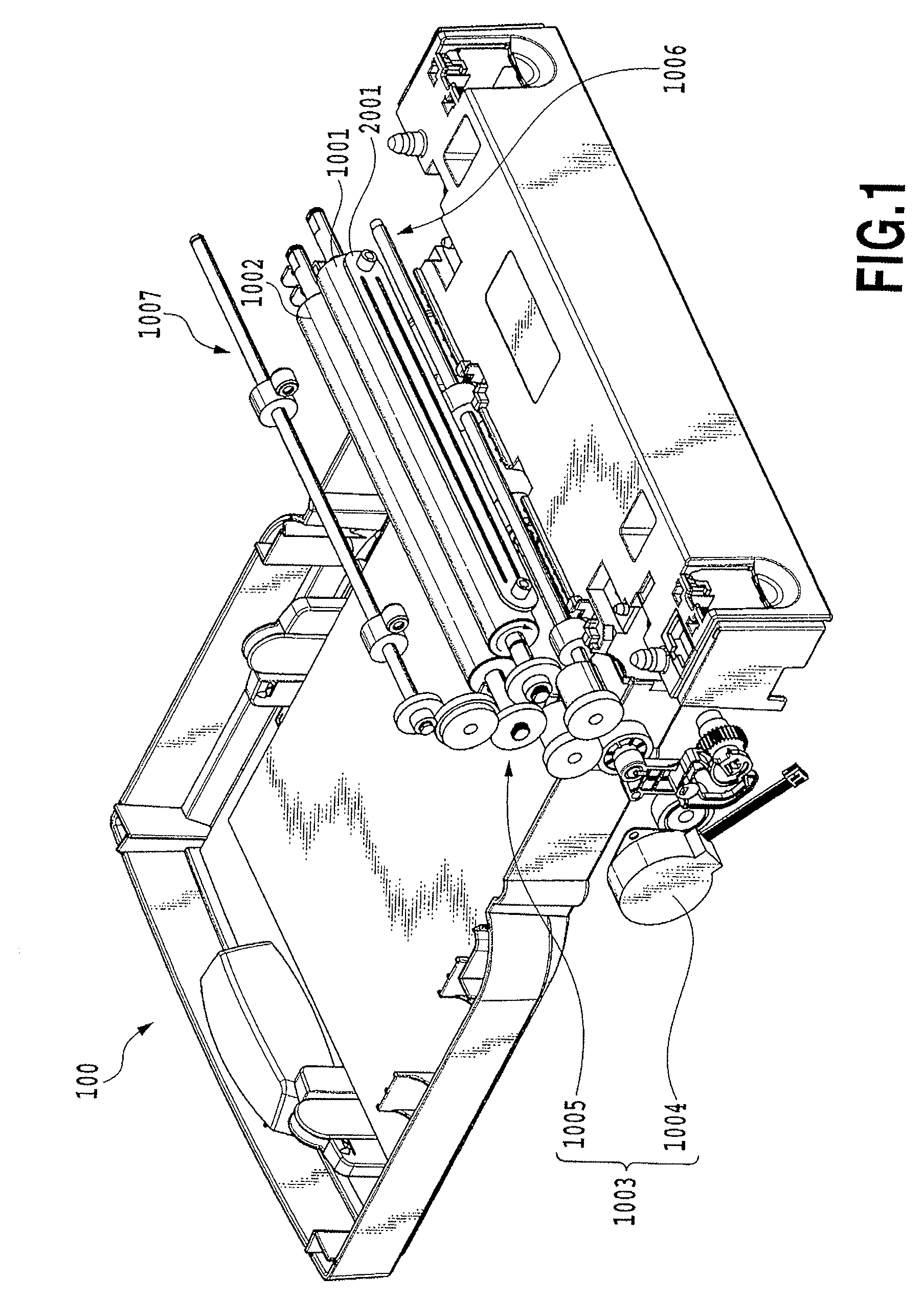
[0071]FIG. 1 is a perspective view showing an overall structure of the embodiment of a liquid application device 100 of the present invention. The liquid application device 100 shown here generally includes liquid application means for applying a predetermined application liquid to a medium (hereinafter also referred to as the application medium) which is an object to which the liquid is applied and liquid supply means for supplying the application liquid to the liquid application means.

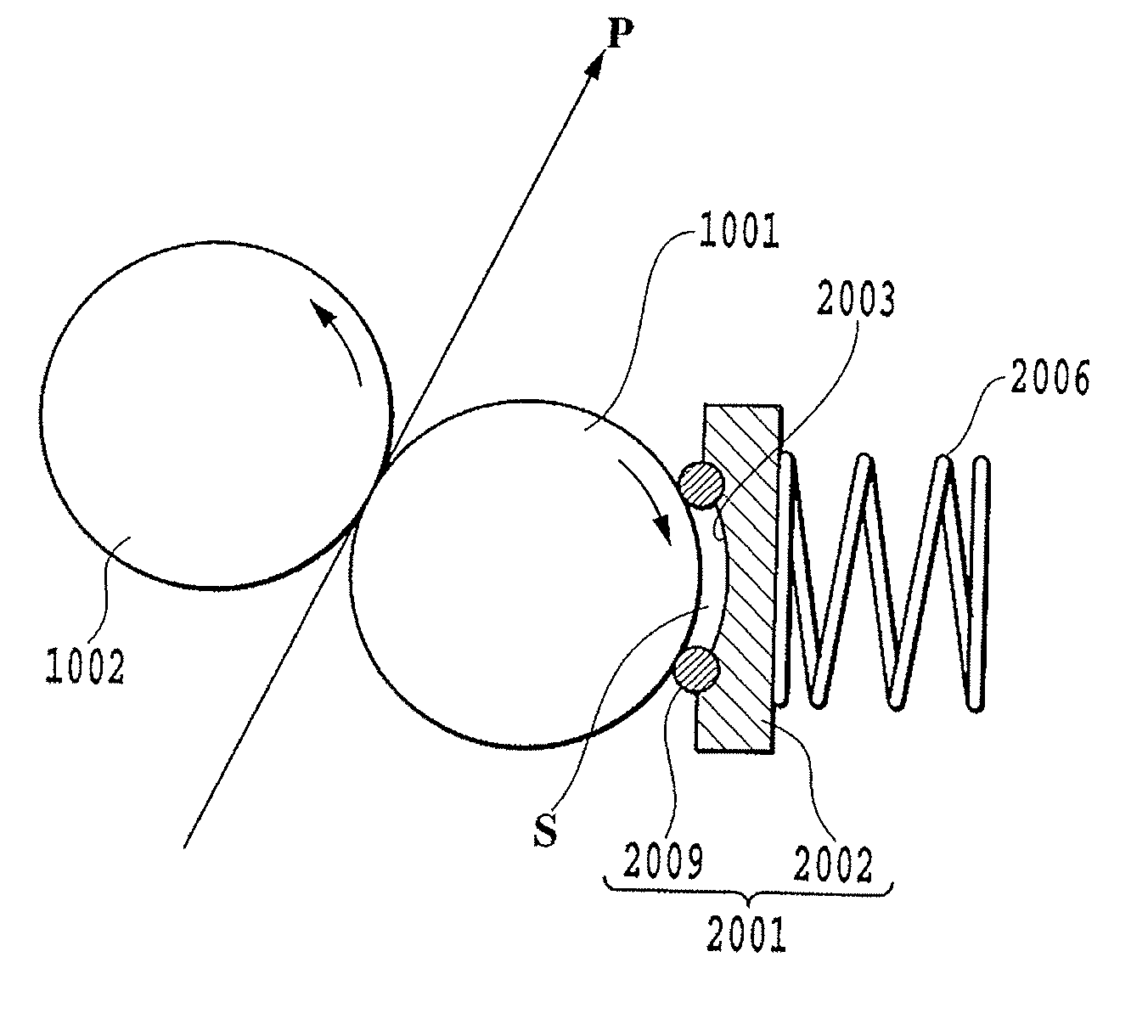
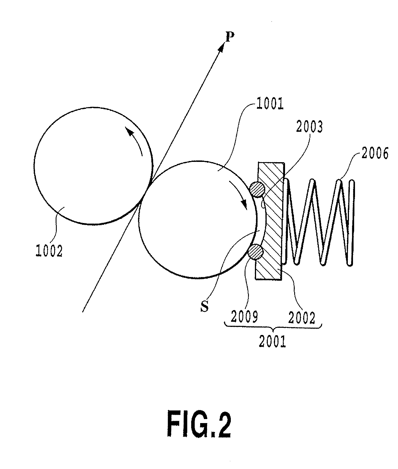
[0072] The liquid application means includes a cylindrical application roller 1001, a cylindrical counter roller (a medium supporting member) 1002 placed so as to face the application roller 1001 and a roller drive mechanism 1003 driving the application roller 1001. The roller drive mechanism 1003 includes a roller drive motor 1004 and a power transmission mechanism 1005 including a gear train for transmitting the driving force of the roller drive motor 1004 to the application roller 1001.

[0073] Th...

second embodiment

[0150]FIG. 20 is a look-up table for deciding the number of preliminary rotations (preliminary rotational time) in this embodiment. The preprocessing operation in this embodiment aims at discharging the thickened matter of the application liquid remaining on the application roller and in the liquid retention member and dust adhering thereto when the device is left unused for a long time when ΔT is 24 hours or more. Namely, this is the control method for collecting the application liquid at least once after the fixed number of preliminary rotations are performed.

[0151]FIG. 16 is a flow chart showing a processing procedure of preprocessing in this embodiment.

[0152] In FIG. 16, processing in steps S41, S42 and S45 to S47 are the same as processing of steps S21, S22 and S23 to S25 shown in FIG. 14, respectively.

[0153] In this embodiment, information on a lapse of time, which indicates a lapse of time between the end time of the previous collection and the start time of the current ap...

third embodiment

[0163] In the first and second embodiments, the preprocessing operation is performed before the start of the current application, after the previous collection is ended and the predetermined time has passed. On the other hands, in this embodiment, the preprocessing operation is controlled according to the lapse of time between the end time of the previous application operation (stop time of the rotation of the application roller for the application operation) before previous collection operation and the start time of the current application operation (start time of the rotation of the application roller for the application operation).

[0164]FIG. 18 is a flow chart showing a processing procedure of preprocessing in this embodiment.

[0165] In step S3 in FIG. 13, when the operation of the pump 3007 is started, the previous stop time information, which indicates the time when the application roller 1001 is stopped, is read from the nonvolatile memory 4012 in step S61. In addition to thi...


PUM


Abstract

The present invention provides a liquid application device, an inkjet recording apparatus and a recording apparatus, which are capable of performing an adequate application initial operation according to the length of waiting time and power-off time, as well as a method of controlling the liquid application device. In the present invention, information on an end time of the previous processing for collecting liquid is read from a nonvolatile memory, current time information indicating the current time is obtained, and information on a lapse of time from the end time of the previous collection to a start time of the current application. Thereafter, the number of preliminary rotations R of an application roller is decided based on the information on the lapse of time with reference to a look-up table. Sequentially, the application roller is rotated by the decided number of preliminary rotations R to perform preprocessing operation.

Description

BACKGROUND OF THE INVENTION [0001] 1. Field of the Invention [0002] The present invention relates to a liquid application device and an inkjet recording apparatus. Particularly, the present invention relates to a liquid application device, an ink jet recording apparatus each applying liquid to a medium for a certain purpose which is, for example, to promote the aggregation of pigment when recording is carried out by using ink containing the pigment as a coloring material. In addition the present invention relates to a method of controlling the liquid application device. [0003] 2. Description of the Related Art [0004] As for an ink jet recording apparatus such as a printer, it is generally known that treatment liquid insolubilizing or coagulating coloring material of ink is used to improve recording quality such as bleeding, density, color tone, offset and the like, and robustness of the image such as waterproof and antiweatherability. [0005] One of methods of applying the treatment ...

Claims


Application Information

Patent Timeline
IPC IPC(8): B41J2/01
CPCB41J11/0015
Inventor MASUYAMA, ATSUHIKOIWASAKI, OSAMUNAKAGAWA, YOSHINORIOSHIO, NAOMIOTSUKA, NAOJISUGIMOTO, HITOSHI
Owner CANON KK
Why Eureka
Try Eureka