Dot data processing apparatus, image processing system, and image data processing apparatus

a technology of image data and processing apparatus, applied in the field of processing images, can solve the problems of inability to carry out image processing using image processing apparatuses with high image processing capabilities, inability to quickly output images, and inability to achieve high-quality images, reduce storage amount to be equipped, and save tim

Inactive Publication Date: 2007-03-29
SEIKO EPSON CORP
View PDF7 Cites 16 Cited by
  • Summary
  • Abstract
  • Description
  • Claims
  • Application Information

AI Technical Summary

Benefits of technology

[0069] In such an image output device, it is possible to determine the pixel group output dot arrangement with a smaller amount of information, which preferably reduces storage amount to be equipped in the image output device.
[0070] With the dot data processing device and method of the present invention, by looking up in a decoding table, output dot arrangements for each of these dot types can be determined, and high quality images can be output. Also, where it is possible to form multiple dot types of dot in this way, data representing the dot on-off state of each pixel for each dot type will ine

Problems solved by technology

As the number of pixels making up an image increases, the time required for image processing becomes longer, making it difficult to output an image quickly.
However, even where image processing has been carried out rapidly, considerable time is required for transfer of the image data, or fo

Method used


Image

  • Dot data processing apparatus, image processing system, and image data processing apparatus
  • Dot data processing apparatus, image processing system, and image data processing apparatus
  • Dot data processing apparatus, image processing system, and image data processing apparatus

Examples


embodiment 1

C. Overview of Image Printing Process of

[0133] C-1. Overview of Multi-value quantization Result Generation Process:

[0134] C-2. Overview of Dot On / Off State Determination Process:

[0135] C-3. Overview of Dither Method:

[0136] C-4. Conceptual Approach of Determining Classification Number:

[0137] C-5. Multi-value Quantization Table Setup Method:

[0138] C-6. Conversion Table Setup Method:

[0139] C-7. Order value matrix Setup Method:

[0140] C-8: Basic Principle Enabling Appropriate Determination of Dot On / Off State from Multi-value Quantization Result Values:

[0141] C-9. Method of Determining Classification Number from Pixel Group Location:

[0142] C-10. Variation Examples:

D. Embodiment 2:

[0143] D-1. Basic Principle of Dot On / Off State Determination Process of Embodiment 2:

[0144] D-2. Dot On / Off State Determination Process of Embodiment 2:

E. Embodiment 3:

[0145] E-1. Basic principle of improving picture quality:

[0146] E-2. Dot on-off state determination process of Embodiment 3:

[0...

embodiment 2

D. Embodiment 2

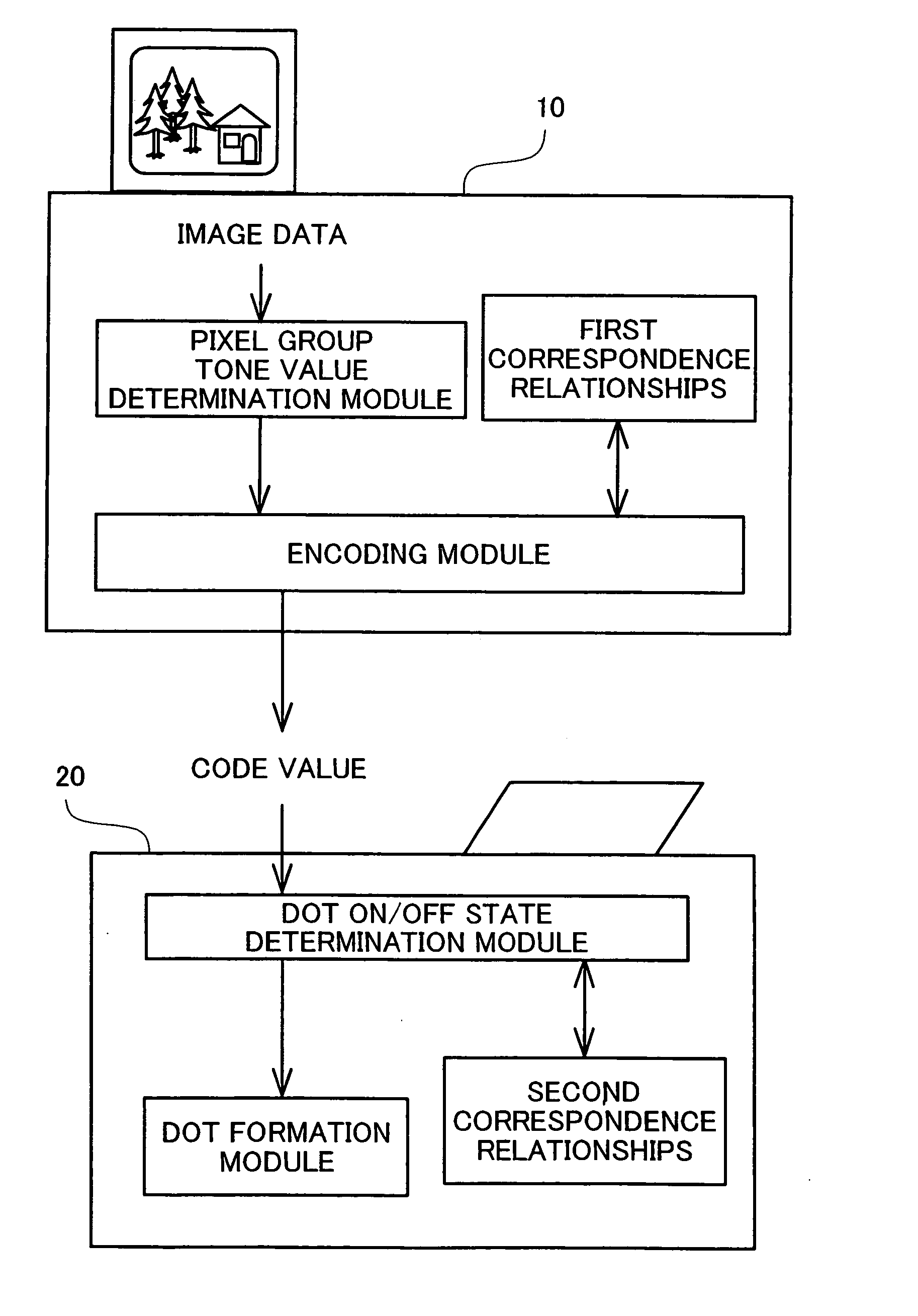
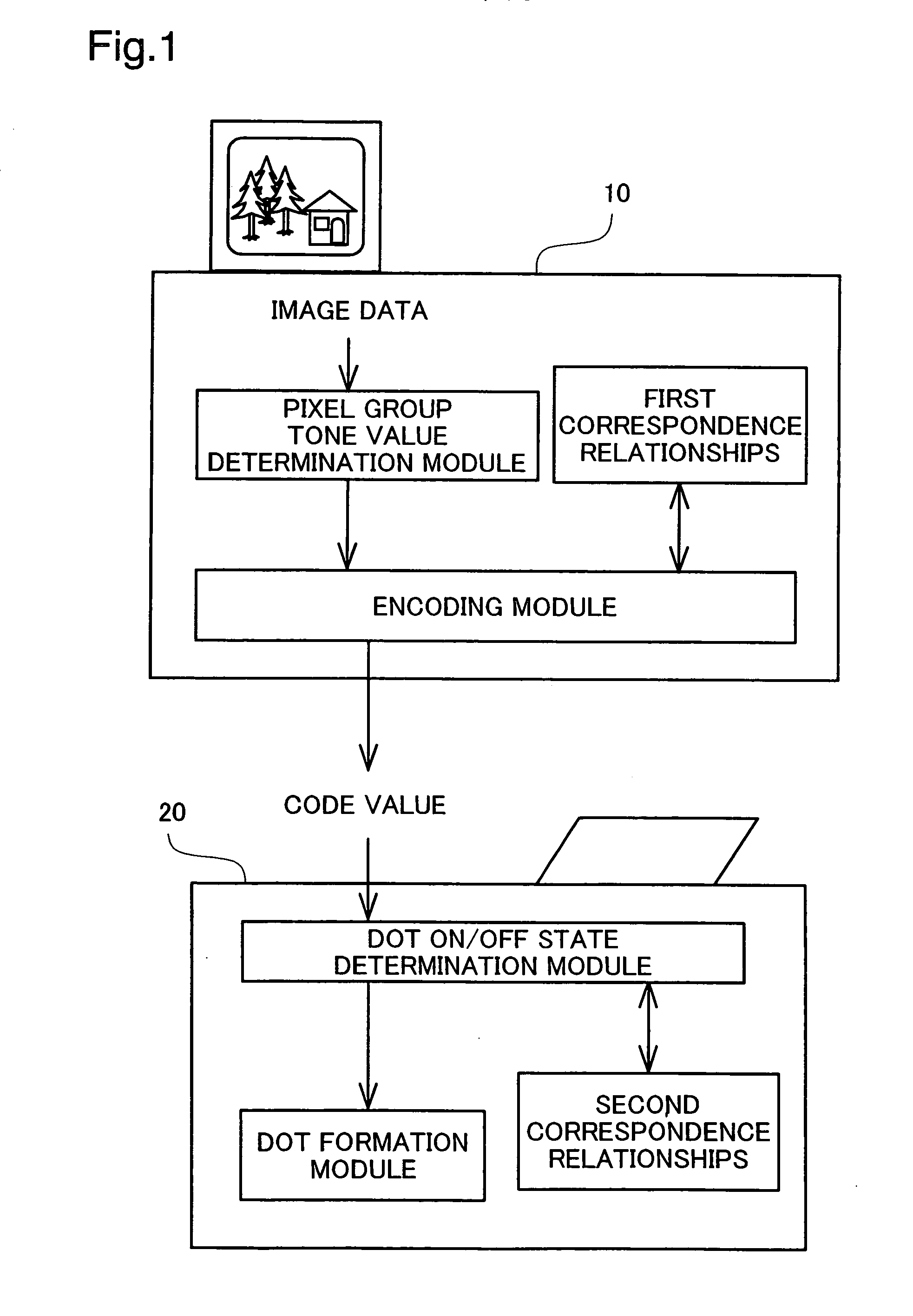
[0326] In the dot on / off state determination process of Embodiment 1 discussed previously, when per-pixel group multi-value quantization result values are received, by means of lookup in the conversion table shown in FIG. 12, they are initially converted to data representing dot counts, and subsequently pixel locations for forming dots within the pixel groups are determined with reference to the order value matrices. However, once per-pixel group multi-value quantization result values have been received, it would be possible to instead determine directly the pixel locations for forming dots within the pixel groups. The dot on / off state determination process of such an Embodiment 2 shall be described below.

D-1. Basic Principle of Dot On / Off State Determination Process of Embodiment 2:

[0327] As shown in FIG. 27, in the dot on / off state determination process of Embodiment 1, once a per-pixel group multi-value quantization result value has been received, the classifica...

embodiment 3

E.

[0337] In the output dot arrangement determination process of the embodiments discussed previously, when determining dot on-off states for pixels from multi-value quantization result values derived on an individual pixel group basis, the dot on-off states were determined using a method based on a dither matrix. Specifically, focusing on the fact that threshold values established in a dither matrix can be viewed as representing the ease of forming a dot, in Embodiment 1, the dot on-off states for pixels were determined on an individual pixel group basis, using a order value matrix established on the basis of a dither matrix. In Embodiment 2, dot data established on the basis of a dither matrix was established in a conversion table, and the dot on-off states for pixels were determined on an individual pixel group basis from the multi-value quantization result values, by means of lookup in the conversion table. Thus, the distributions of dots obtained by means of the dot on-off state...


PUM


Abstract

The present invention provides a dot data processing apparatus for generating data of dots to be formed on a printing medium. The apparatus includes: a decoding preparation unit that prepares a decoding table for pixel groups, each of the pixel groups grouping together a plurality of pixels that constitute a unit of dot formation, the table containing output dot arrangements and code values in a number of identifiers assigned to the pixel groups, the output dot arrangements and code values being associated, the output dot arrangements representing the dot on-off states for the pixels in the pixel groups, the code values assuming a prescribed range of values; a code value receiving unit that receives code values derived as a result of encoding of image data representing an image with a prescribed tone number, the encoding being performed for the each pixel group as an encoding unit; a decoding unit that acquires the output dot arrangement based on the received code value and the identifier assigned to the pixel group, by means of lookup in the decoding table; and a dot data output unit that outputs dot data which represents an arrangement of dots to be formed on a printing medium, in accordance with the acquired output dot arrangement.

Description

TECHNICAL FIELD [0001] This invention relates in general to a technology for processing an image on the basis of image data, and relates in particular to a technology for processing pixel groups as process unit each of which composed of a plurality of pixels, for processing data of dots to be formed on a print medium. BACKGROUND ART [0002] Image output devices that output images by forming dots on output media of various kinds, such as a printing medium or liquid crystal screen, are widely used as output devices of various kinds of imaging machines. Such image output devices handle images finely divided into tiny areas termed pixels, with dots being formed on the pixels. Where dots have been formed on pixels, viewed in terms of individual pixels, each pixel can of course only assume either a dot on state or a dot off state. However, viewed in terms of somewhat larger areas, it is possible for the density of the formed dots to be coarser or finer, and by means of varying this dot for...

Claims


Application Information

Patent Timeline
IPC IPC(8): H04N1/40B41J2/52G06T5/00H04N1/405
CPCH04N1/4057
Inventor KAKUTANI, TOSHIAKI
Owner SEIKO EPSON CORP
Why Eureka
Try Eureka