Light modulation apparatus and light modulator control method

a light modulator and light modulation technology, applied in the direction of optics, instruments, optical elements, etc., can solve the problems of generating errors, modulating apparatus using ln modulators having a problem of the deterioration of the accuracy of output light signals, and the inability to continue controlling the point where the light intensity of output light signals becomes the weakest extinction state as the bias poin

Inactive Publication Date: 2007-03-29
YOKOGAWA ELECTRIC CORP
View PDF1 Cites 12 Cited by
  • Summary
  • Abstract
  • Description
  • Claims
  • Application Information

AI Technical Summary

Benefits of technology

[0015] It is an object of the present invention to provide a light modulation apparatus and a light modulator control method which can adjust the bias point of a light modulator to a suitable position-at the time of a burst mode.

Problems solved by technology

Consequently, there is the possibility of generating an error at the time of a light communication.
Although the light modulating apparatus using the LN modulator has the advantages of being excellent in the extinction ratio and of the realizability of a wide area ideal light modulation having no chirping in comparison with those of the light modulating apparatus using the EA modulator, the light modulating apparatus using the LN modulator has a problem of the deterioration of the accuracy of the output light signal thereof because temperature drifts and drifts with time are generated.
However, in the techniques described in the Japanese Patents No. 2642499 and No. 3398929 mentioned above, because the operation at the time of the burst mode, in which the mark rate is not constant, is not taken into consideration, there is a problem in which it is impossible to continue controlling the point where the light intensity of the output light signal becomes the weakest extinction state as the bias point, and to perform the efficient modulation of the output light signal.

Method used


Image

  • Light modulation apparatus and light modulator control method
  • Light modulation apparatus and light modulator control method
  • Light modulation apparatus and light modulator control method

Examples


Embodiment Construction

[0036] In the following, the best mode for implementing the present invention is described with reference to the attached drawings. However, the scope of invention is not limited to the shown examples.

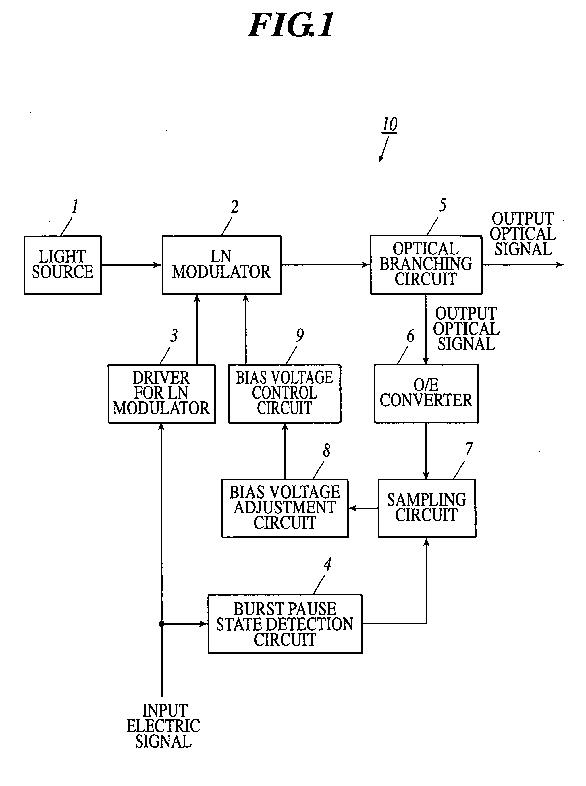
[0037] First, FIG. 1 is referred to for describing the configuration of the light modulation apparatus 10. In addition, the detailed descriptions of the components similar to the configuration described in FIG. 4 mentioned above are omitted. In the following, the characteristic configurations and operations of the present embodiment are described.

[0038] As shown in FIG. 1, the light modulation apparatus 10 is composed of a light source 1, an LN modulator 2, a driver 3 for LN modulator, a burst pause state detection circuit 4, an optical branching circuit 5, an optical / electric (O / E) converter 6, a sampling circuit 7, a bias voltage adjustment circuit 8 and the bias control circuit 9.

[0039] The light source 1 is light emission means such as a laser diode, which emits a light of a fix...


PUM

PropertyMeasurementUnit
fixed wavelengthaaaaaaaaaa
bias voltageaaaaaaaaaa
electricaaaaaaaaaa

Abstract

A light modulation apparatus including a Mach-Zehnder type light modulator, a driver for modulator outputting a control signal according to an input electric signal, a light branching circuit branching the output light signal, and a bias control circuit applying a bias voltage to the light modulator based on the branched light signal, the apparatus further comprises: a burst pause state detection circuit detecting a pause state of a burst signal included in the input electric signal; a photoelectric transducer converting an output light signal branched by the light branching circuit into an electric signal; a sampling circuit extracting the electric signal converted while the pause state is detected by the burst pause state; and a bias voltage adjustment circuit adjusting a bias voltage value of the bias voltage based on a voltage level of the extracted electric signal.

Description

BACKGROUND OF THE INVENTION [0001] 1. Field of the Invention The present invention relates to a light modulation apparatus and a light modulator control method of an external modulation system used for light communication systems, and more particularly to a light modulation apparatus and a light modulator control method using a Mach-Zehnder type light modulator. [0002] 2. Description of Related Art [0003] In recent years, as the light communication systems have advanced, a light modulation apparatus capable of stably outputting a high frequency output light signal (light pulses) has been demanded. For example, a light modulation apparatus equipped with an external modulator such as an electro-absorption (EA) modulator, an LN modulator using a material having an electro-optical effect (Pockels effect) of lithium niobate (LiNbO3) or the like as a substrate, or the like has been put to practical use. [0004]FIG. 3 is a diagram showing the configuration of a light modulation apparatus 10...

Claims


Application Information

Patent Timeline
Patent Type & Authority Applications(United States)
IPC IPC(8): G02F1/03
CPCG02F1/0123G02F1/2255G02F2203/21G02F2202/20G02F2001/212G02F1/212G02F1/225
Inventor MIURA, AKIRAUCHIDA, KENJIIKEZAWA, KATSUYAMATSUURA, HIROYUKITOYAMA, AKIRAKOBAYASHI, TOSHIAKIYAKIHARA, TSUYOSHIDOI, KOUSUKE
Owner YOKOGAWA ELECTRIC CORP
Why Eureka
Try Eureka