Contact inspection device, and contact inspection device and method for magnetic disk device
a technology of contact inspection and magnetic disk, which is applied in the direction of instruments, heat measurement, specific gravity measurement, etc., can solve the problems of inability to evaluate two modes separately, inability to accurately capture detection signals, and limited friction and wear, so as to improve the ease of replacement of magnetic disk 1 and limit the attenuation of ae
- Summary
- Abstract
- Description
- Claims
- Application Information
AI Technical Summary
Benefits of technology
Problems solved by technology
Method used
Image
Examples
embodiment 1
[0054] Embodiment 1 of the present invention will be described with reference to FIGS. 1 to 7.
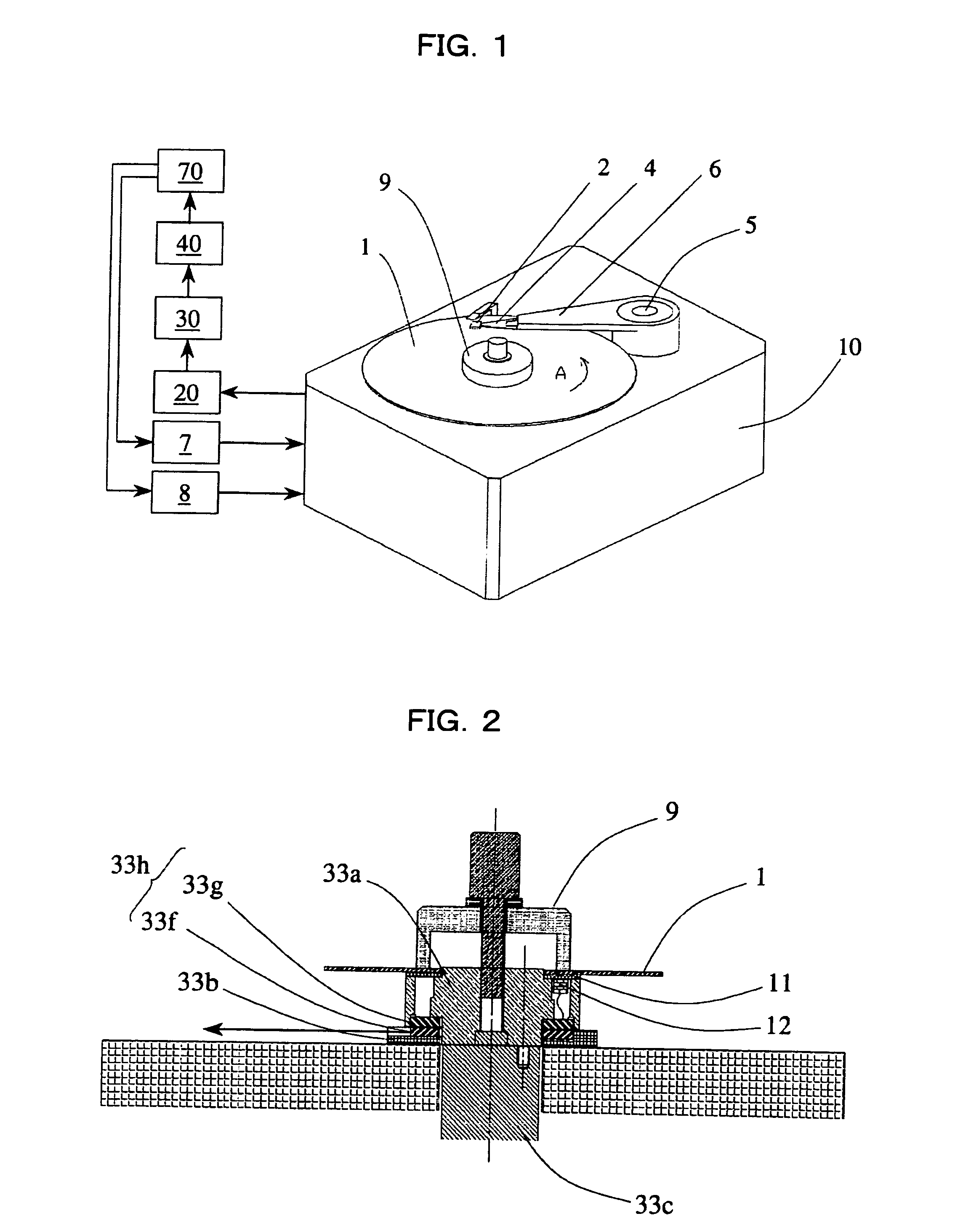
[0055]FIG. 1 is a block diagram showing a contact inspection device in Embodiment 1 of the present invention. Portions corresponding to those in the conventional art shown in FIGS. 12 to 14 are indicated by the same reference numerals, and will not be described in detail.
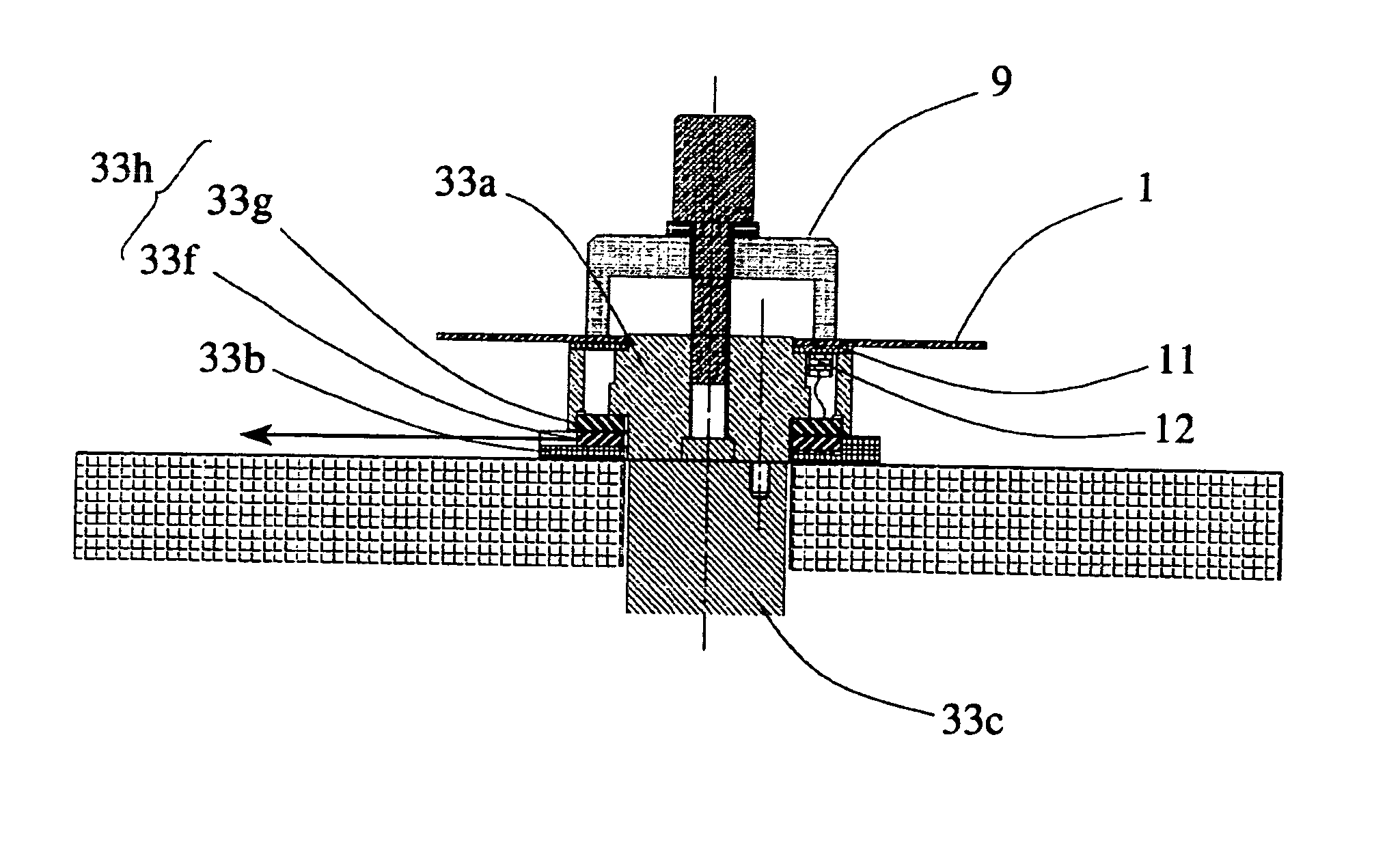
[0056] In FIG. 1, reference numeral 1 denotes a magnetic disk; reference numeral 2 a slider; reference numeral 4 a suspension; reference numeral 5 a voice coil motor; reference numeral 6 an arm; reference numeral 7 a spindle drive circuit; reference numeral 8 an actuator drive circuit; and reference numeral 9 a disk clamp. Reference numerals 10 denote a frame. The magnetic disk 1 is fixed on a spindle (not shown) in the frame 10 by the disk clamp 9. Reference numerals 20 denote a wide-band amplifier; reference numerals 30 a filter circuit; reference numerals 40 an effective value computation circuit provided as an effecti...
embodiment 2
[0072]FIG. 8 shows a block diagram of a contact inspection device in Embodiment 2 of the present invention. The contact inspection device shown in FIG. 8 is basically the same as the contact inspection device of Embodiment 1 shown in FIG. 1. In the contact inspection device shown in FIG. 8, however, an AE sensor 12b is also fixed on the arm 6 side. When the arm 6 is turned, the suspension 4 is lifted to a ramp block 13 or moves down from the ramp block 13 to directly unload the slider 2 from the magnetic disk 1 or directly load the slider 2 onto the magnetic disk 1. In FIG. 8, reference character 12b denotes an AE sensor fixed by bonding to the arm 6; reference character 20b a wide-band amplifier which amplifies a signal from the AE sensor 12b; reference character 30b a filter circuit for filtering a signal from the wide-band amplifier 20b; and reference character 40b an effective value computation circuit provided as an effective value computation device for computing the effective...
PUM
 Abstract
Description
Claims
Application Information
 - R&D
- Intellectual Property
- Life Sciences
- Materials
- Tech Scout
- Unparalleled Data Quality
- Higher Quality Content
- 60% Fewer Hallucinations
Browse by: Latest US Patents, China's latest patents, Technical Efficacy Thesaurus, Application Domain, Technology Topic, Popular Technical Reports.
© 2025 PatSnap. All rights reserved.Legal|Privacy policy|Modern Slavery Act Transparency Statement|Sitemap|About US| Contact US: help@patsnap.com


