
Vehicle window glass with terminal

a technology for vehicle window glass and terminals, applied in vehicle cleaning, vehicle maintenance, coupling device connection, etc., can solve problems such as cracks and adverse effects on humans or the environment, and achieve the effect of preventing cracks and reducing heat generation of terminals

Pending Publication Date: 2021-07-29
ASAHI GLASS CO LTD
View PDF8 Cites 1 Cited by
  • Summary
  • Abstract
  • Description
  • Claims
  • Application Information

AI Technical Summary

Benefits of technology

The present invention is about a vehicle window glass with a terminal that prevents cracks and peeling during hot and cold cycles. The terminal is connected to an electrically conductive layer on the surface of the glass through lead-free solder. This prevents a large amount of current from flowing in the terminal, which could generate heat. The invention also controls the attenuation of signals in the terminal. Overall, the invention ensures durability and signal stability of the vehicle window glass.

Problems solved by technology

Whereas, it has been recently pointed out that lead has an adverse effect on humans or environment.
For this reason, when an electrically conductive layer is connected to a terminal by lead-free solder, there is caused a problem that a crack could be formed, or peeling could occur in a glass plate in a hot and cold cycle test for evaluation of a vehicle window glass.

Method used


Image

  • Vehicle window glass with terminal
  • Vehicle window glass with terminal
  • Vehicle window glass with terminal

Examples


first embodiment

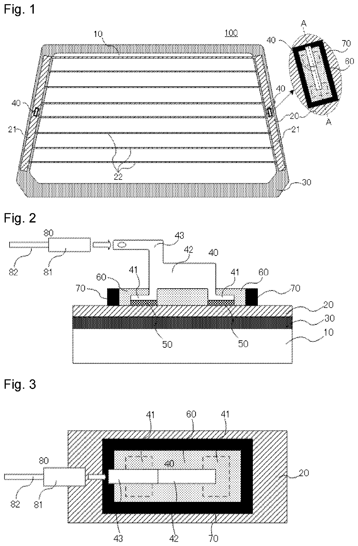
[0025]As shown in FIG. 1, the vehicle window glass with a terminal 100 according to a first embodiment of the present invention includes an electrically conductive layer 20 disposed on at least one of primary surfaces of a vehicle window glass 10, and a terminal 40 connected to the electrically conductive layer 20.

[0026]The vehicle window glass 10 may be, for example, formed of soda lime glass, borosilicate glass, alkali-free glass or quartz glass without particular limitations. Among them, soda lime glass is particularly preferred. The glass plate 10 may be formed of either non-tempered glass or tempered glass. Non-tempered glass is prepared by forming molten glass in a plate shape and annealing the formed glass. Tempered glass is prepared by forming a compressive stress layer on a surface of non-tempered glass. Tempered glass may be either physically tempered glass (such as glass tempered by air quenching) or chemically tempered glass. When physically tempered glass is used, glass...

second embodiment

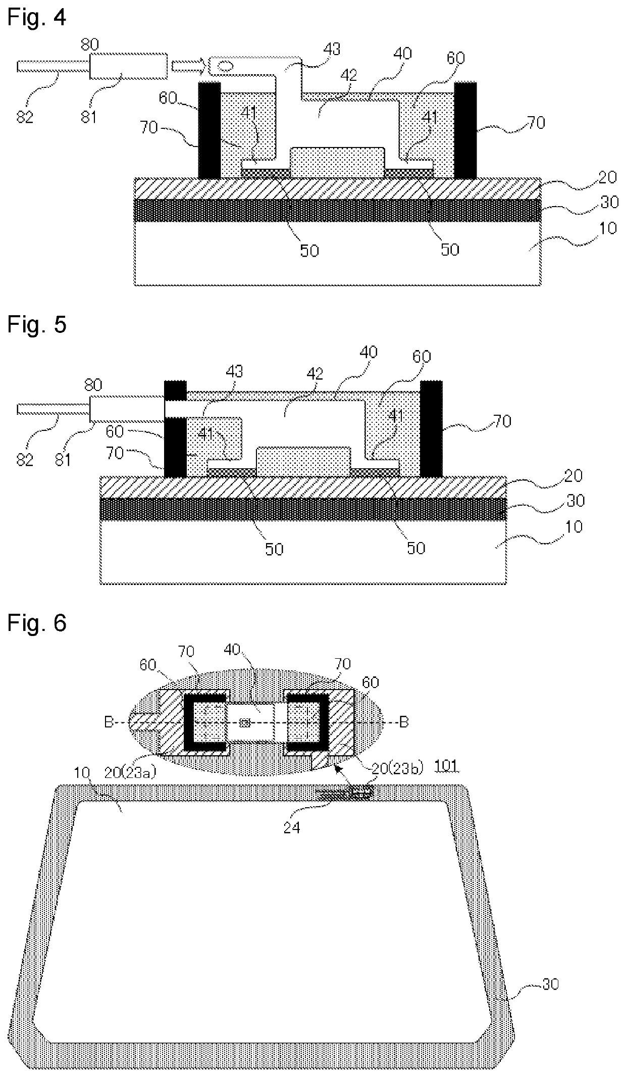
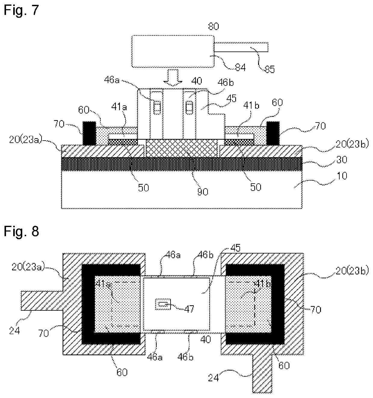
[0040]As shown in FIG. 6, the vehicle window glass with a terminal 101 according to a second embodiment of the present invention includes an electrode 23 formed of an electrically conductive layer 20 disposed on at least one of principle surfaces of a vehicle window glass 10, and an antenna conductor 24 extending from the electrode 23, and further includes a terminal 40 connected to the electrode 23. Elements common to those of the vehicle window glass with a terminal 10 according to the first embodiment are denoted by like reference numerals, and explanation of the common elements will be omitted.

[0041]In the vehicle window glass with a terminal 101 according to the second embodiment, the electrode 23 includes a positive electrode 23a, and a negative electrode 23b disposed at a position apart from the positive electrode by a certain distance. It should be noted that the positions of the positive electrode 23a and the negative electrode 23b shown in this figure may be reversed. The ...


PUM


Abstract

A vehicle window glass with a terminal includes a glass plate, and a terminal connected, by lead-free solder, to an electrically conductive layer disposed on a surface of the glass plate, wherein the terminal at least one leg connected to the electrically conductive layer by the lead-free solder, and wherein at least one portion of the leg is covered with a thermal insulating member.

Description

CROSS-REFERENCE TO RELATED APPLICATIONS[0001]This application is a continuation of PCT Application No. PCT / JP2019 / 020738, filed on May 24, 2019, which is based upon and claims the benefit of priority from Japanese Patent Application No. 2018-107844 filed on Jun. 5, 2018. The contents of those applications are incorporated herein by reference in their entireties.TECHNICAL FIELD[0002]The present invention relates to a vehicle window glass with a terminal.BACKGROUND ART[0003]A vehicle window glass has an electrically conductive layer made of a conductive material, disposed on a glass surface to serve as, e.g., a defogger for the purpose of defogging, or an antenna for a radio receiver, a TV receiver or radio communication. In the case of a defogger for the purpose of defogging, silver paste or another material is baked on a glass surface to dispose a heater pattern or bus bars thereon. In the case of an antenna, silver paste or another material is likewise baked on a glass surface to d...

Claims


Application Information

Patent Timeline
Patent Type & Authority Applications(United States)
IPC IPC(8): H01Q1/12H01R12/57H01R4/70H01R12/75B60J1/00H05B3/86
CPCH01Q1/1278H01R12/57H01R4/70B60S1/026B60J1/002H05B3/86H01R12/75H01Q1/002H01R2201/26H01R2101/00H05B2203/002
Inventor KUWAHARA, YOSHIYUKIMINAMIYA, YUUKOU
Owner ASAHI GLASS CO LTD
Learn More