Magnetic recording head including main magnetic pole layer, return path layer, and coil layer

a recording head and magnetic pole technology, applied in the direction of data recording, instruments, heads with metal sheet cores, etc., can solve the problems of avoiding one or more of the problems, and achieve the effect of improving recording efficiency and recording efficiency

Active Publication Date: 2007-03-29
TDK CORPARATION
View PDF3 Cites 2 Cited by
  • Summary
  • Abstract
  • Description
  • Claims
  • Application Information

AI Technical Summary

Benefits of technology

[0029] The present embodiments are directed to a magnetic recording head, which may obviate one or more of the problems due to the limitations and disadvantages of the related art. For example, in a present embodiment the magnetic recording head provided is capable of maintaining high recording efficiency and improving the recording efficiency by preventing leakage magnetic field from a magnetic pole end base. In a present embodiment, a magnetic recording head includes a main magnetic pole layer and a return path layer that face each other with a predetermined distance therebetween in a film thickness direction at a facing surface that faces a recording medium. A coil layer applies a recording magnetic field to the main magnetic pole layer. A yoke layer that is magnetically connected with the main magnetic pole layer is formed between the main magnetic pole layer and the return path layer. An extending front end portion that extends toward the main magnetic pole layer is formed in the return path layer. The yoke layer is disposed inside the extending front end portion in a height direction. The main magnetic pole layer includes a front end that extends inwardly from the facing surface in the height direction with the width size of a track and a rear end that widens from a base formed inside the front end in the height direction and extends inwardly in the height direction, and the yoke layer is formed on the surface of the main magnetic pole layer facing the return path layer to cover the base.
[0035] In the magnetic recording head, the yoke layer is formed between the main magnetic pole layer and return path layer, and also formed on the surface of the return path layer facing the main magnetic pole layer such that it covers the base of the main magnetic pole layer. Accordingly, leakage magnetic flux φ resulting from magnetic saturation at the base is prevented by the yoke layer and it is possible to make the magnetic flux φ of the leakage magnetic field difficult to flow into a recording medium, and also the yoke layer can be disposed relatively closer to a facing surface facing the recording medium than the base of the main magnetic pole layer although the base is disposed very far from the facing surface, so that the magnetic flux φ of the recording magnetic field is effectively induced at the front end of the main magnetic pole layer by the yoke layer. The magnetic flux φ of the recording magnetic field can be effectively concentrated on the front end and recording efficiency can be improved. Although the base of the main magnetic poly layer is disposed very far from the facing surface to improve the recording efficiency, the recording efficiency can be improved by the coil layer.
[0038] Although the leakage magnetic flux φ of from the front end or the surroundings of the yoke layer flows toward the facing surface, the leakage magnetic flux φ is interrupted by the extending front end portion of the return path layer, and therefore the magnetic flux φ of the leakage magnetic field is effectively prevented from reaching the recoding medium. Therefore, a recording signal in an approximate track is effectively protected from being removed.
[0039] In the perpendicular magnetic recording head, the recording efficiency is improved by concentrating the magnetic flux φ of the recording magnetic field on the front end of the main magnetic pole layer. The removing of a recording signal in the approximate track is effectively prevented by preventing the leakage magnetic flux φ of out of the yoke layer from reaching the recording medium, so that both the improvement in the recording efficiency and the prevention of the removing of a signal in the proximate track can be achieved at the same time.

Problems solved by technology

The present embodiments are directed to a magnetic recording head, which may obviate one or more of the problems due to the limitations and disadvantages of the related art.

Method used


Image

  • Magnetic recording head including main magnetic pole layer, return path layer, and coil layer
  • Magnetic recording head including main magnetic pole layer, return path layer, and coil layer
  • Magnetic recording head including main magnetic pole layer, return path layer, and coil layer

Examples


first embodiment

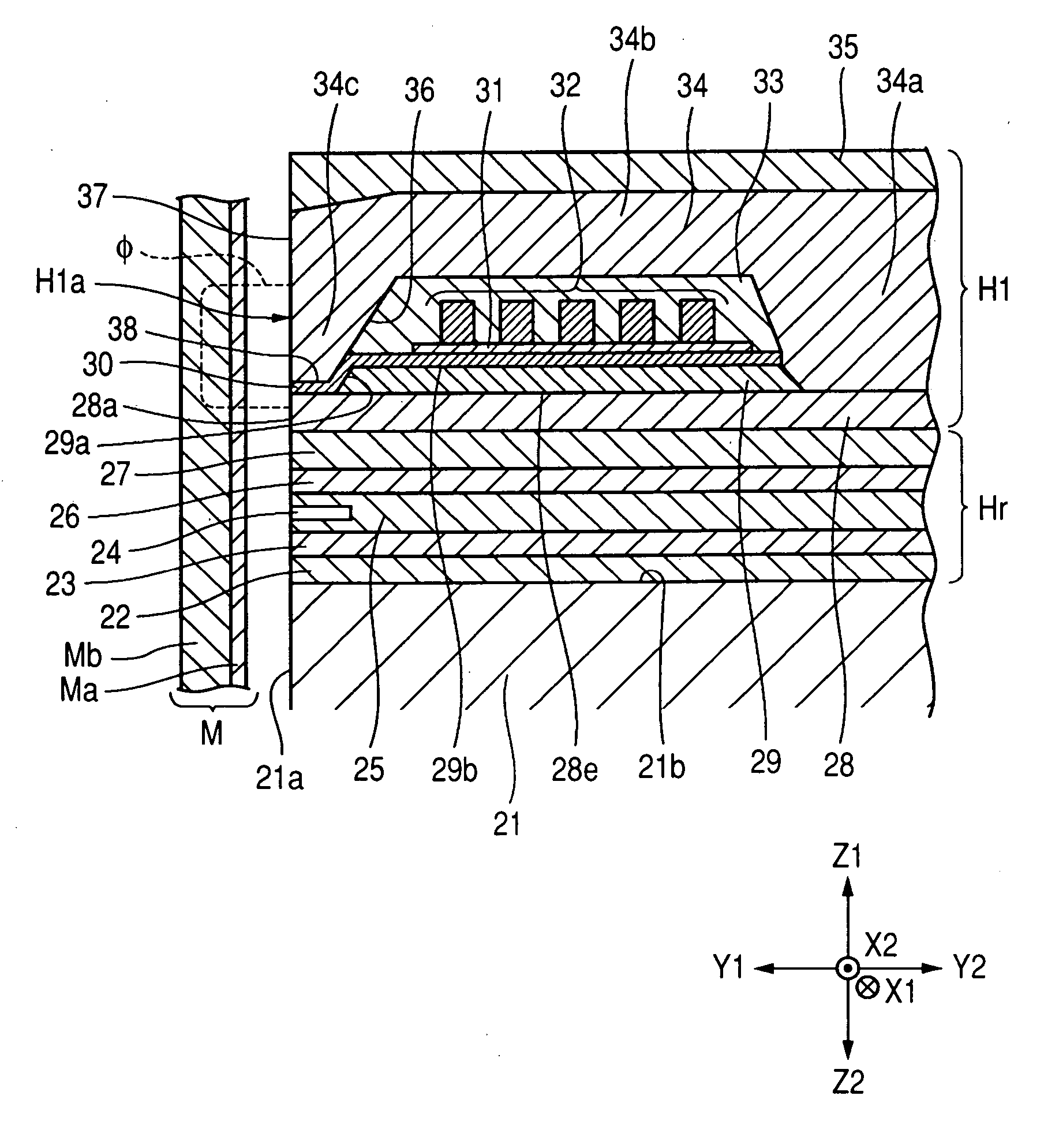
[0049]FIG. 1 is a partial perpendicular magnetic recording cross-sectional view illustrating a configuration of a perpendicular magnetic recording head according to a magnetic recording head of the invention.

[0050] A perpendicular magnetic recording magnetic recording head H1 shown in FIG. 1 applies perpendicular magnetic recording magnetic field to a recording medium M and magnetizes a hard film Ma of the recording medium M.

[0051] The recording medium may be, for example, a disc and include a hard film Ma with high coercivity on the surface and a soft film Mb with high magnetic permeability inside the hard film Ma. Further, the disc rotates about its central axis.

[0052] A slider 21 is formed of a nonmagnetic material, such as Al2O3, Ti, or the like, and a facing surface 21a faces the recording medium M. If the recording medium M rotates, the slider 21 rises from the surface of the recording medium M due to airflow on the surface or slides on the recording medium M.

[0053] A nonma...

second embodiment

[0086]FIG. 3 is an exploded perpendicular magnetic recording cross-sectional view showing a configuration of a perpendicular magnetic recording head according a magnetic recording head on the invention.

[0087] A perpendicular magnetic recording head H2 shown in FIG. 3 includes the same components as the perpendicular magnetic recording head H1 shown in FIG. 1. Therefore, in the perpendicular magnetic recording head H2, the same components as in the perpendicular magnetic recording head H1 are designated by the same reference numerals and not described below.

[0088] The perpendicular magnetic recording head H2 shown in FIG. 3 is different from the perpendicular magnetic recording head H1 shown in FIG. 1 as for the shape of the extending front end portion 34c defined in the return path layer 34. As shown in FIG. 3, at a facing surface H2a, the main magnetic pole layer 28 faces the extending front end portion 34c of the return path layer 34 through the gap layer 30, that is, at a predet...

third embodiment

[0090]FIG. 4 is an exploded perpendicular magnetic recording cross-sectional view illustrating a configuration of a perpendicular magnetic recording head according to a magnetic recording head of the invention.

[0091] A perpendicular magnetic recording head H3 shown in FIG. 4 includes the same components as the perpendicular magnetic recording head H1 shown in FIG. 1. In the perpendicular magnetic recording head H3, the same components as in the perpendicular magnetic recording head Hi shown in FIG. 1 are designated by the same reference numerals and not described below.

[0092] The perpendicular magnetic recording head H3 shown in FIG. 4 has a difference from the perpendicular magnetic recording head H1 shown in FIG. 1 that the main magnetic pole layer 28, yoke layer 29, gap layer 30, coil layer 32, and return path layer 34 are formed upward (Z1-Z2 direction on the separating layer 27 (in the Z1 direction in FIG. 1) in the reverse order).

[0093] For example, as shown in FIG. 4, the p...


PUM

PropertyMeasurementUnit
heightaaaaaaaaaa
thicknessaaaaaaaaaa
recording magnetic fieldaaaaaaaaaa

Abstract

A magnetic recording head is provided. The magnetic recording head comprises a main magnetic pole layer, a return path layer, and a coil layer. A facing surface faces a recording medium. A yoke layer is formed between the main magnetic pole layer and the return path layer. An extending front end portion is formed in the return path layer and the yoke layer is disposed inside the extending front end portion in a height direction. The main magnetic pole layer includes a front end and a rear end and the yoke layer is formed on the surface of the main magnetic pole layer to cover the base.

Description

[0001] This application claims the benefit of Japanese Patent Application 2005-277817 filed Sep. 26, 2005, which hereby is incorporated by reference. BACKGROUND [0002] 1. Field [0003] The present embodiments relate to a magnetic recording head including main magnetic pole layer, return path layer, and coil layer. [0004] 2. Related Art [0005]FIG. 6 is a perpendicular magnetic recording cross-sectional view of a configuration of a magnetic recording head in the related art disclosed in JP-A-10-269533. [0006] A known magnetic recording head H500 shown in FIG. 6 is formed at a trailing portion (the Z1 direction in the drawing) of a nonmagnetic insulating layer 612 formed on a substrate. A configuration including a playback head for reading is disclosed in JP-A-10-269533, but the playback head is not shown in FIG. 6 to help easy understanding of the following description. [0007] As shown in FIG. 6, in the magnetic recording head H500 in the related art, a main magnetic pole layer 524 is ...

Claims


Application Information

Patent Timeline
Patent Type & Authority Applications(United States)
IPC IPC(8): G11B5/147
CPCG11B5/1278G11B5/313G11B5/3116
Inventor YAZAWA, HISAYUKI
Owner TDK CORPARATION
Why Eureka
Try Eureka