

Cutting block for surgical navigation
- Summary
- Abstract
- Description
- Claims
- Application Information
AI Technical Summary
Benefits of technology
Problems solved by technology
Method used
Image

Examples
Embodiment Construction
[0044] The embodiments of the present teachings described below are not intended to be exhaustive or to limit the teachings to the precise forms disclosed in the following detailed description. Rather, the embodiments are chosen and described so that others skilled in the art may appreciate and understand the principles and practices of the present teachings.
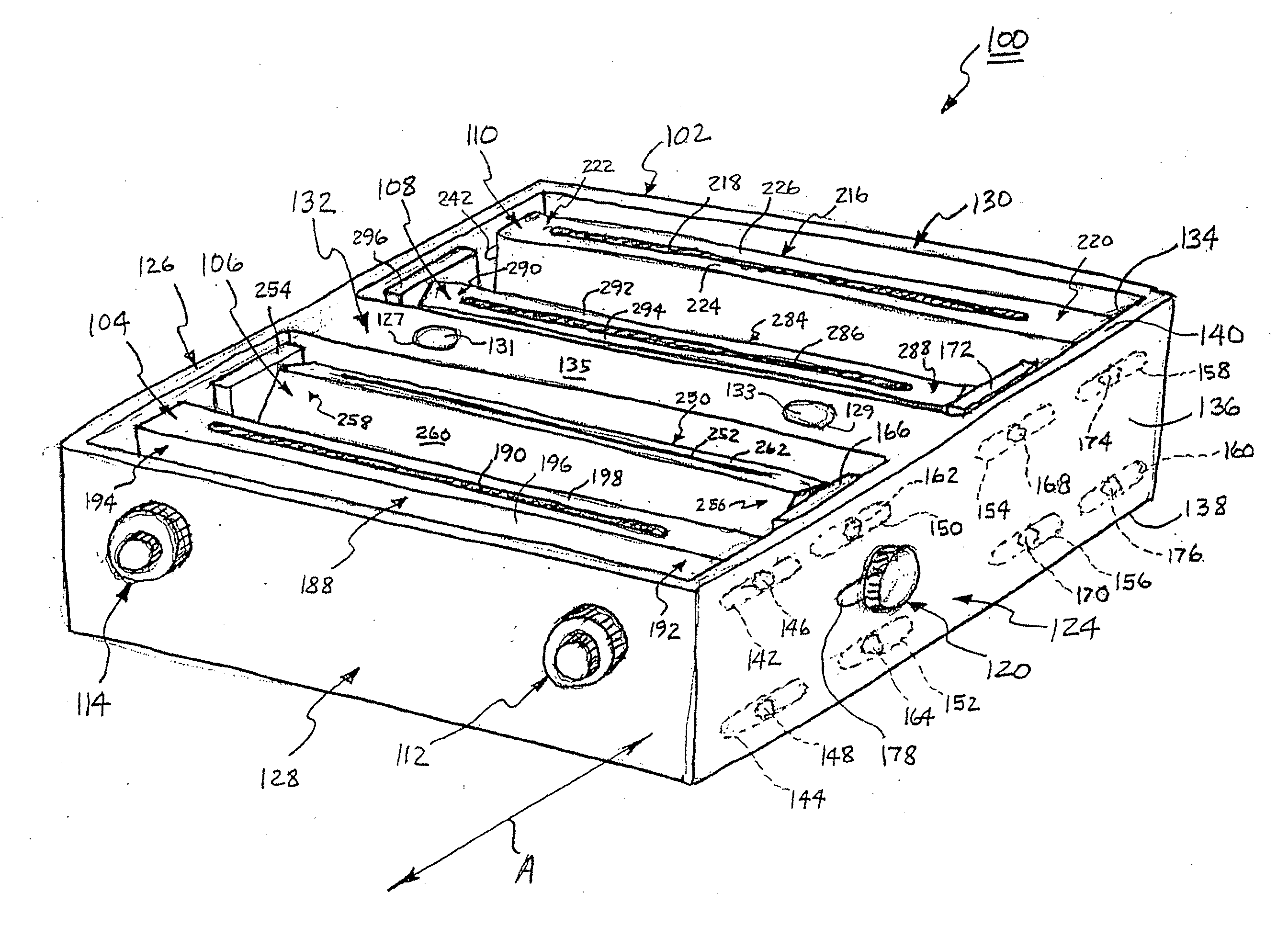
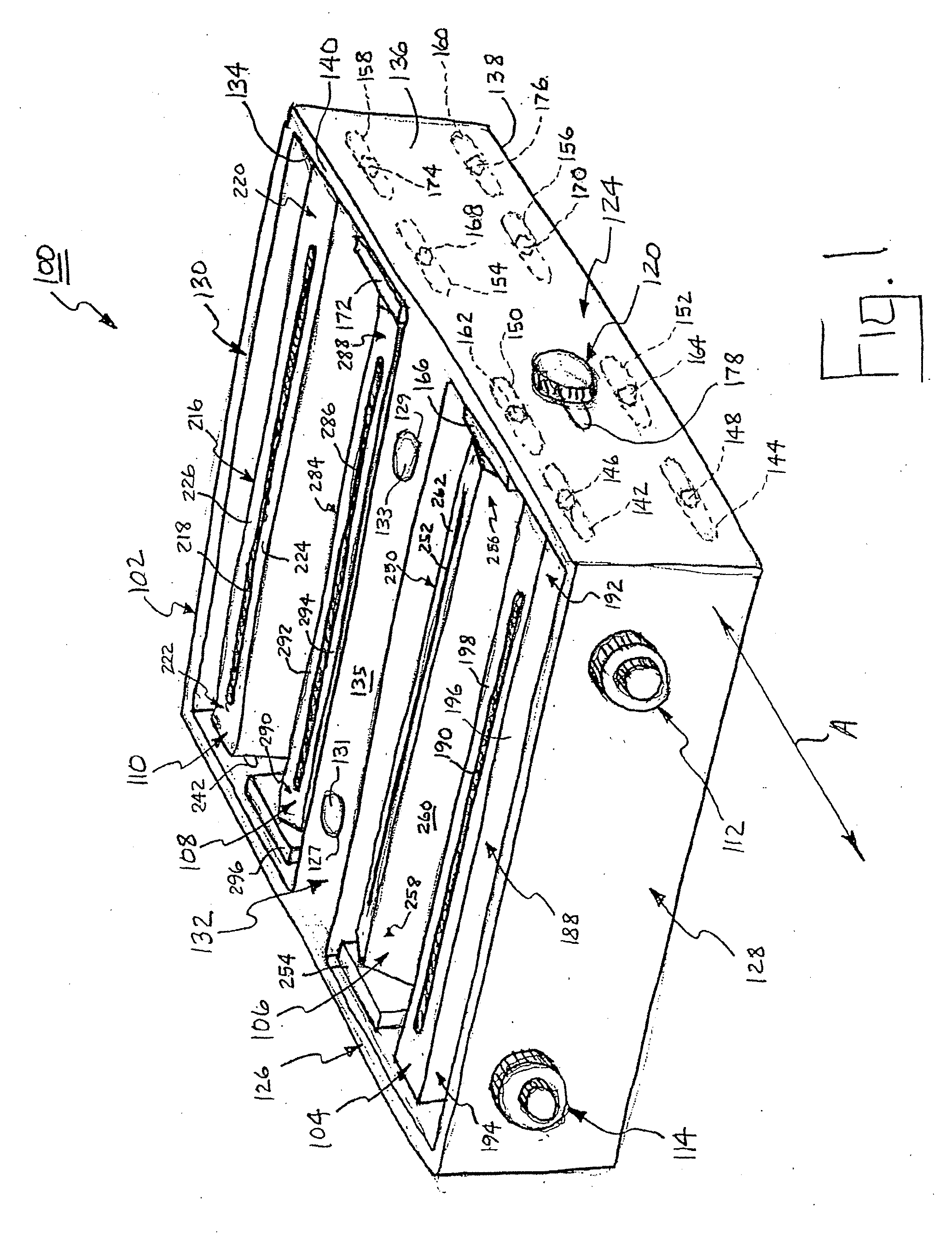
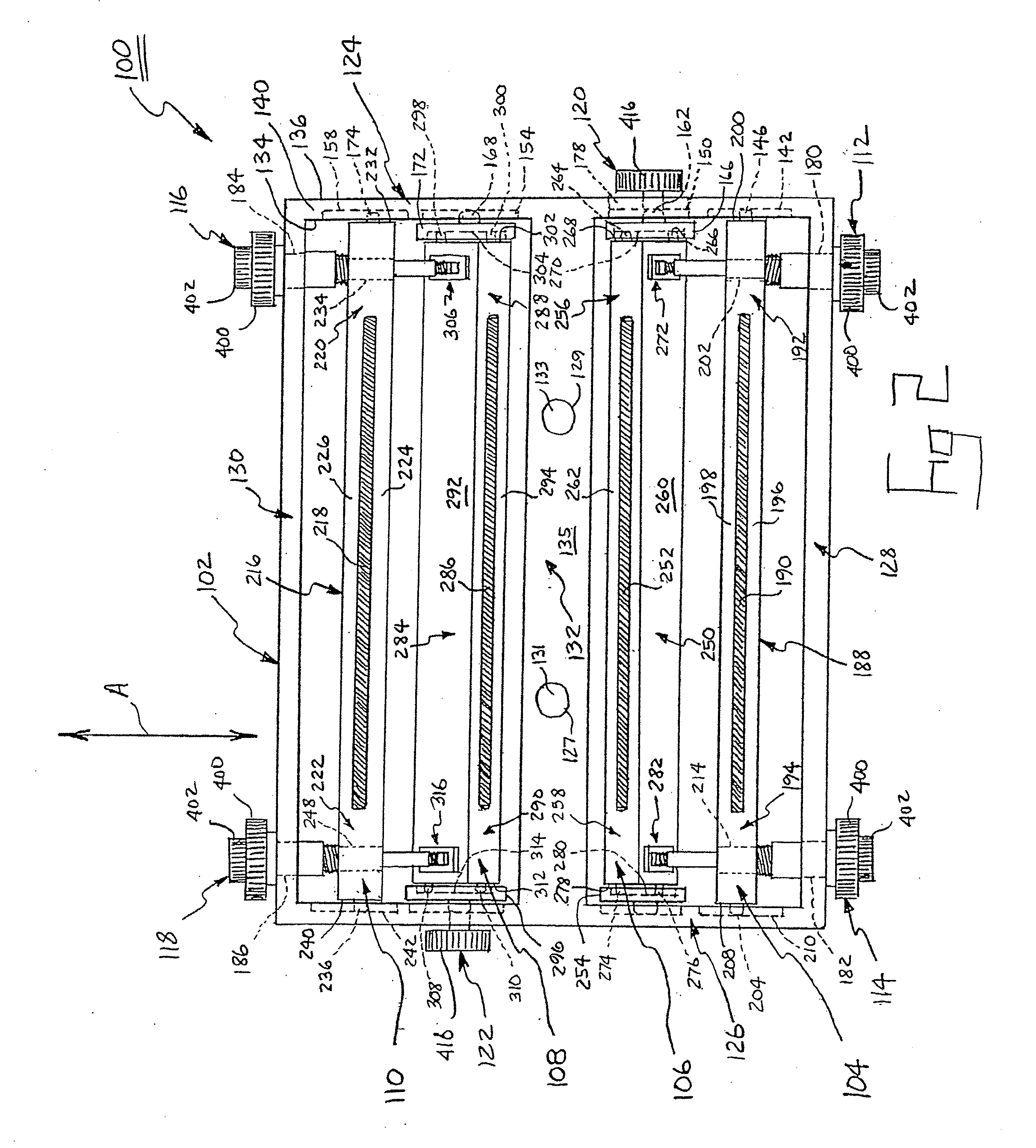
[0045] Referring now to FIGS. 1-3, one embodiment of a cutting block 100 for use in the present system is shown. Cutting block 100 generally includes a frame 102, four adjustable guides 104, 106, 108, 110, four linear adjustors 112, 114, 116, 118, and two angular adjustors 120, 122. It should be understood that the number of guides and adjustors may be different from the number described herein. More specifically, one skilled in the art could readily adapt the teachings of this disclosure to provide a cutting block with one, two, three, or more than four guides with a corresponding number of linear and angular adjustors to posi...
PUM
 Abstract
Description
Claims
Application Information