Method of manufacturing a pressure intensifying tool and tool produced thereby

a technology of pressure intensification and manufacturing method, which is applied in the direction of total factory control, programme control, instruments, etc., can solve the problems of non-uniform or complex surface geometries, complicated compaction process, and relatively time-consuming entire molding process, and achieve low production runs and high part accuracy

Active Publication Date: 2007-03-29
THE BOEING CO
View PDF12 Cites 16 Cited by
  • Summary
  • Abstract
  • Description
  • Claims
  • Application Information

AI Technical Summary

Benefits of technology

[0010] The manufacturing process of the present invention advantageously eliminates the need for fabricating a mold and using the mold to form the tool. Direct digital manufacturing of the pressure intensifier tool assures that dimensions and surface features of the tool very nearly approach the theoretical design values for the tool. The manufacturing process allows the tool to be directly digitally manufactured using a CAD drawing file and readily available rapid prototyping techniques, making the process particularly suitable for low production runs requiring high part accuracy.

Problems solved by technology

Certain features of composite structures, such as non-uniform or complex surface geometries, complicate the compaction process.
The entire molding process was therefore relatively time and labor intensive.
The resources needed to fabricate and prepare the mold represented substantial manufacturing costs in the case of short production runs, such as those encountered in the aircraft industry, for example.

Method used


Image

  • Method of manufacturing a pressure intensifying tool and tool produced thereby
  • Method of manufacturing a pressure intensifying tool and tool produced thereby
  • Method of manufacturing a pressure intensifying tool and tool produced thereby

Examples


Embodiment Construction

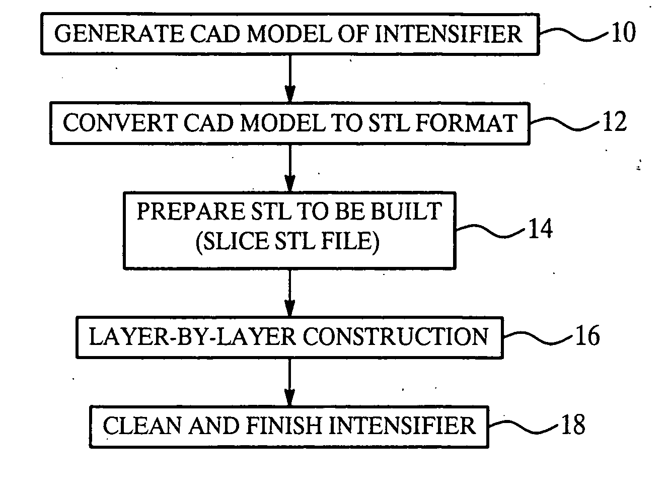
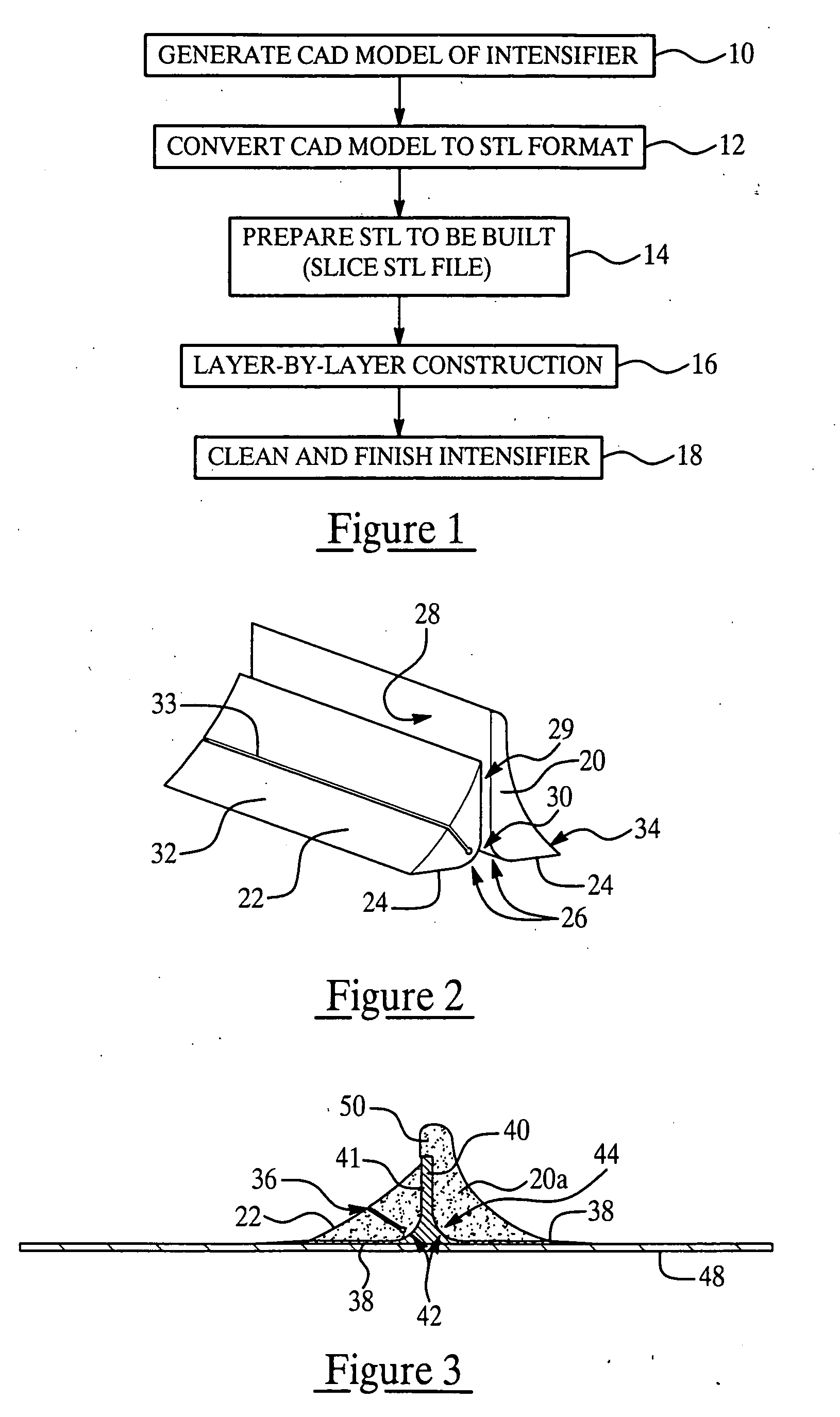
[0017]FIG. 1 broadly shows the steps of a method for manufacturing a pressure intensifier tool used for directing pressure applied to compact areas of plastic part lay up during co-curing or co-bonding of the plies and binder that form the layup. As shown at step 10, the first step involves generating a digital model of the tool, which is preferably performed by generating a CAD (Computer Aided Design) model of the tool using any of a variety of commercially available software. Other techniques can be employed, of course, to produce the digital file, providing that they result in accurately describing the theoretical dimensions and surface geometry of the desired tool. The CAD software is essentially a surface modeler that builds a number of mathematical patches or surfaces that, when joined together, form the shape and dimensions of the desired tool. In order to assure that the tool is properly and completely modeled, the CAD file is converted to STL (Stereolithography) file format...


PUM


Abstract

A tool used to direct the pressure applied to features of a plastic laminate part layup during co-curing or co-bonding is manufactured using direct digital manufacturing techniques. A CAD drawing representing the tool is generated and converted into digital data file suitable for controlling the operation of a rapid prototyping machine. The tool is formed in the rapid prototyping machine by additive layering of material until the features and dimensions of the layered material correspond to the CAD drawing. The resulting tool exhibits geometries and dimensions virtually identical to the theoretical dimensions of the CAD model of the tool.

Description

FEDERALLY SPONSORED RESEARCH OR DEVELOPMENT [0001] This invention made with Government support under contract number N00014-01-2-0001 awarded by the United States Navy. The Government has certain rights in this invention.FIELD OF THE INVENTION [0002] This invention generally relates to manufacturing processes and tools used to fabricate composite laminate parts, especially those employing plastics, and deals more particularly with a method of manufacturing a tool for directing the compaction pressure applied to certain features of a plastic laminate part layup during co-curing or co-bonding thereof. BACKGROUND OF THE INVENTION [0003] Composite structures are widely used in high performance applications because of their light weight, high strength, high stiffness and superior fatigue resistance. These structures broadly comprise a combination of dissimilar constituent materials bonded together by a binder, but are most commonly formed by a thermosetting resin matrix in combination wi...

Claims


Application Information

Patent Timeline
Patent Type & Authority Applications(United States)
IPC IPC(8): G06F19/00
CPCG05B19/4099G05B2219/49003G05B2219/49017G05B2219/49013G05B2219/49011B33Y50/00B33Y80/00Y02P90/02
Inventor FROESCHNER, NEAL A.PISZAR, JIM S.
Owner THE BOEING CO
Why Eureka
Try Eureka