Method for operation of a converter system

a converter system and converter technology, applied in the direction of electric power transfer ac network, single network parallel feeding arrangement, position/direction control, etc., can solve the problems of not considering the efficiency of the pcu's in the system, and the amount of power being input to the pcu's is not constant, so as to achieve fast disabling and enable

Active Publication Date: 2007-03-29
GAMESA INNOVATION & TECH SA +1
View PDF5 Cites 63 Cited by
  • Summary
  • Abstract
  • Description
  • Claims
  • Application Information

AI Technical Summary

Benefits of technology

[0033] It is an advantage that the wind turbine system may comprise disabling and / or enabling means such as generator inverters and / or grid inverters for short term disabling and / enabling of the converter modules. The disabling and / or enabling may be achieved by applying disabling / enabling signals to the generator inverters and / or grid inverters. The wind turbine may also comprise disabling and / or enabling means such as matrix converters also being capable of fast disabling and / or fast enabling by applying disabling / enabling signals to the matrix converter.
[0034] It is another advantage that the wind turbine system may comprise means such as contactors for disconnecting the converter module from the generator and the utility grid for the purpose of long term disabling of the converter modules.
[0035] In relation to the above-mentioned advantages, it is an advantage that the wind turbine system may comprise means such as phase shifters for phase shifting the Pulse-Width-Modulation (PWM) patterns of the enabled converter modules.

Problems solved by technology

However, WO 2004 / 030189 neither considers how to improve the mean-time-between-failure of the power conversion units, nor does it consider how to manage changes in the produced amount of electric power being inputted to PCU's, and thus, WO 2004 / 030189 does not consider how to improve the efficiency of the PCU's in a system wherein the amount of power being input to the PCU's is not constant over time.

Method used


Image

  • Method for operation of a converter system
  • Method for operation of a converter system
  • Method for operation of a converter system

Examples


Embodiment Construction

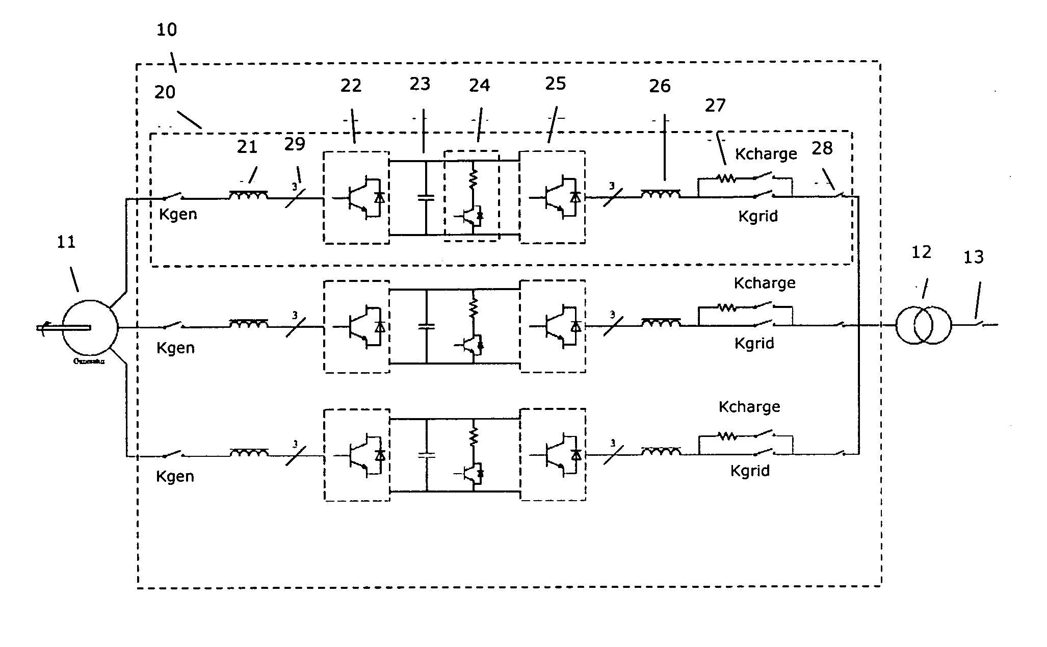
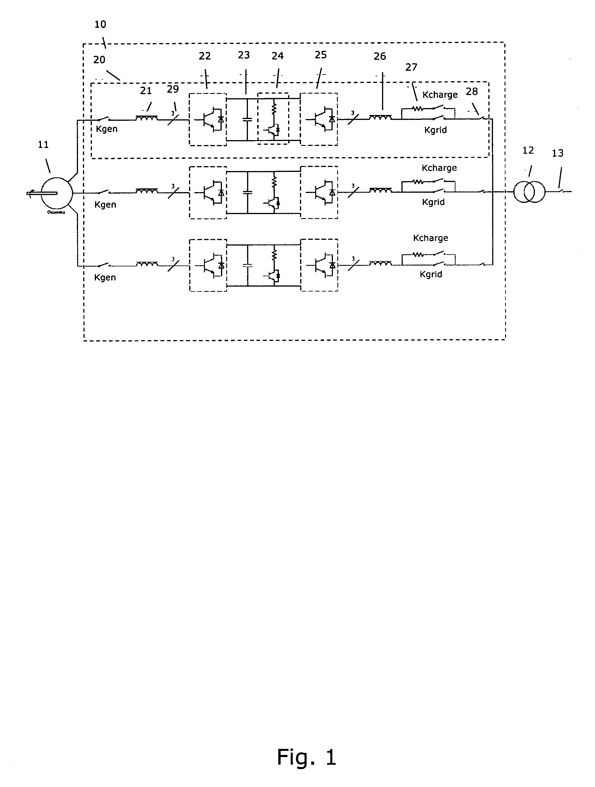
[0040]FIG. 1 illustrates a converter system 10 comprising 3 converter modules 20 connected in parallel. FIG. 1 also illustrates a generator 11 of the wind turbine, a transformer 12 connecting the output from the converter system 10 to the utility grid and a circuit breaker 13.

[0041] The converter module 20 comprises a generator contactor Kgen for disconnecting the generator from the electronics of the converter module 20. The converter module also comprises an inductor 21 for smoothing the generator current, a generator inverter 22 for transforming the AC signal from the generator 11 to a DC signal, a DC link capacitor 23 for smoothing out variations of the DC signal, a brake chopper 24 for dissipation of residual power, a grid inverter for transforming the DC signal to an AC signal, and an inductor 26 which in combination with capacitors (not shown) serves to reduce harmonics of the voltage signal being applied to the utility grid. The converter module 20 further comprises a charg...


PUM


Abstract

The present invention relates to a method for operating a converter system of a wind turbine, wherein the converter system includes converter modules capable of converting electric power produced by a generator to electric power applicable to a utility grid. The converter modules include generator inverters and grid inverters. The method determines the enabling/disabling of the converter modules in response to a parameter related to the variable amount of electric power being produced by the generator. Advantages of the present invention are optimisation of power efficiency of the converter modules and improved reliability of the converter modules. Another advantage is the capability of fast enabling and disabling of the converter modules.

Description

FIELD OF THE INVENTION [0001] The present invention relates to the field of electric power generation of a utility grid connected wind turbine, and specifically to wind turbines and electric power converter systems comprising converter modules for supplying the electric power to the utility grid. BACKGROUND OF THE INVENTION [0002] A first aspect of wind turbines relates to electric power efficiency of the converter system. Even a small improvement of the power efficiency may be significant for the profitability of the investment in wind turbines due to increased power production. [0003] A second aspect of wind turbines relates to the reliability of the converter system. Improved reliability of the converter system increases the reliability of the wind turbine, thus increasing the mean-time-between-failure (MTBF) of the wind turbine. The increase of the mean-time-between-failure consequently decreases service costs and increases the power production over time, which is important for ...

Claims


Application Information

Patent Timeline
Patent Type & Authority Applications(United States)
IPC IPC(8): G05D11/00
CPCH02J3/386Y02E10/763H02J2300/28H02J3/381Y02E10/76H02J3/46
Inventor LLORENTE GONZALEZ, JOSE IGNACIOANDRESEN, BJORNBIRK, JENS
Owner GAMESA INNOVATION & TECH SA
Why Eureka
Try Eureka