Most acoustic wave chemical detection sensors, for example, rely on the
mass sensitivity of the sensor in conjunction with a chemically selective
coating that absorbs the vapors of interest resulting in an increased
mass loading of the SAW sensor.
What happens is that it becomes contaminated with water, acids, burnt and un-burnt fuel, carbon particles and
sludge so that it can no longer provide the desired degree of protection for engine components.
Most oil filters in modern vehicles do not remove all the contaminants.
A filter can only remove
solid particles above a certain size.
It cannot remove water, acids, or fuel
dilution, all of which pass through the full-flow filter just as readily as the oil.
There is a limit, however, to the amount of
contamination that even the best
oil can neutralize, and there comes a time when the only satisfactory procedure is to drain the oil and replenish the engine with a new charge.
The question is now “how often should engine oil be changed?” Unfortunately, there is no simple answer to this question.
From the foregoing discussion, it is apparent that oil is changed not because it has deteriorated, but because it has become contaminated with various harmful substances, and that the greater the rate at which such substances enter the oil, the sooner an oil change is necessary.
There are two different types of fuel
combustion in engines: efficient
combustion or clean burning; and inefficient combustion or dirty burning.
Thus, during the burning of
gasoline in engines, a potential problem exists with respect to
soot, resins, acids, and water formation.
If
combustion products function past the pistons and manage to penetrate the
crankcase oil, then a problem of dirty, contaminated oil will exist.
If the oil is allowed to become too dirty and contaminated,
sludge deposits can form, thereby resulting in plugged
piston rings,
oil pump screens and oil filters.
The really tough lubricating job is the engine, which typically experiences only short runs with numerous stops and starts, especially in
cold weather.
The worst conditions for both the engine and the oil are the very conditions under which the great majority of passenger cars are used most of the time.
Primarily due to the cost of laboratory analysis, however, these tests are only performed on a routine basis, i.e. monthly or at each oil drain interval.
Lube oil within a healthy engine degrades at a
slow rate with normal use.
It is at the second function, however, where lab analysis fails and does not provide sufficient failure warnings such as
coolant leaks and stress related
metal failures.
Equipment is normally sampled on a monthly basis and while this is a sufficient interval to safely monitor the lube condition, many times this frequency is not sufficient in detecting engine problems.
On the second day, unknown to the maintenance personnel and the oil lab, a
coolant leak develops within the engine.
Within the next several days, the
coolant leak degrades the oil within the engine to the point that it causes wear to occur to bearings and other parts of the engine.
Two days after receiving this report, the operator notices that the oil is becoming cloudy and that the engine is making a little steam.
The routine monthly sampling of the used oil was not effective in achieving its goal.
Diesel engines are particularly hard on oil because of oxidation from acidic combustion.
The frequency changes caused by small changes in viscosity of highly viscous liquids, however, are very small.
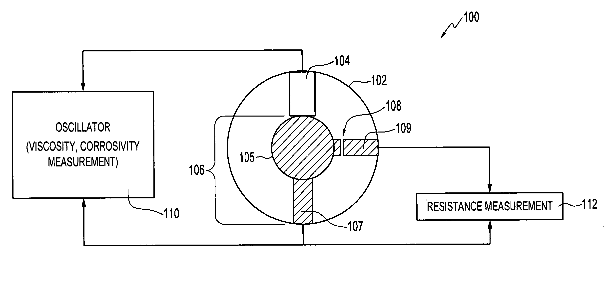
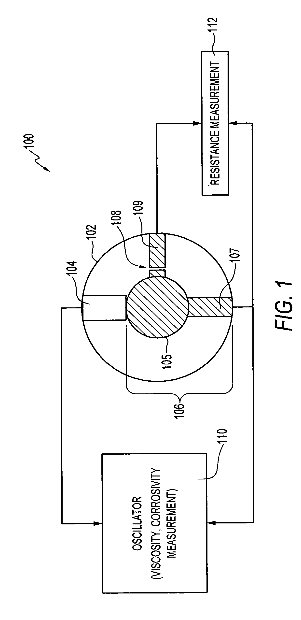
Because of the highly viscous loading, the
signal from a sensor oscillator is very “noisy” and the accuracy of such measurement systems is very poor.
One of the problems with acoustic wave devices utilized in oil monitoring applications, for example, is that frequency changes caused by small changes in the viscosity of highly viscous fluids, are very small.
Because of highly viscous loading, the
signal from an oscillator associated with the acoustic wave sensor device is very noisy and the accuracy of such measurements is very poor.

