Blow-by gas recirculation system

a blow-by gas and recirculation system technology, which is applied in the direction of charge feed system, non-fuel substance addition to fuel, combustion engine, etc., can solve the problems of increased pressure in the interior of the crankcase, water contained in the blow-by gas may freeze, and the increase of the blow-by gas on the downstream side of the throttle valve cannot be effectively discharged into the intake air passage, etc., to achieve the effect of limiting the exposure of the throttle valv

Inactive Publication Date: 2007-04-05
DENSO CORP +1
View PDF9 Cites 15 Cited by
  • Summary
  • Abstract
  • Description
  • Claims
  • Application Information

AI Technical Summary

Benefits of technology

[0011] The present invention addresses the above disadvantage. Thus, it is an objective of the present invention to provide a blow-by gas recirculation system, which can limit exposure of a throttle valve to blow-by gas.

Problems solved by technology

Thus, when the opening degree of the throttle valve is increased to cause an increase in the blow-by gas, the increased blow-by gas on the downstream side of the throttle valve cannot be effectively discharged into the intake air passage.
Therefore, the accumulated blow-by gas, which is not discharged through the PCV valve, causes an increase in the pressure in the interior of the crankcase.
Also, the water contained in the blow-by gas may freeze at the low temperature to limit smooth rotation of the throttle valve.
However, due to a relation between the heat quantity generated by the heat source and the external temperature, the freezing may not be sufficiently limited in some cases.
However, even in this technique, the backflow of the blow-by gas into the intake air passage on the upstream side of the throttle valve may still occur.

Method used


Image

  • Blow-by gas recirculation system
  • Blow-by gas recirculation system
  • Blow-by gas recirculation system

Examples


first embodiment

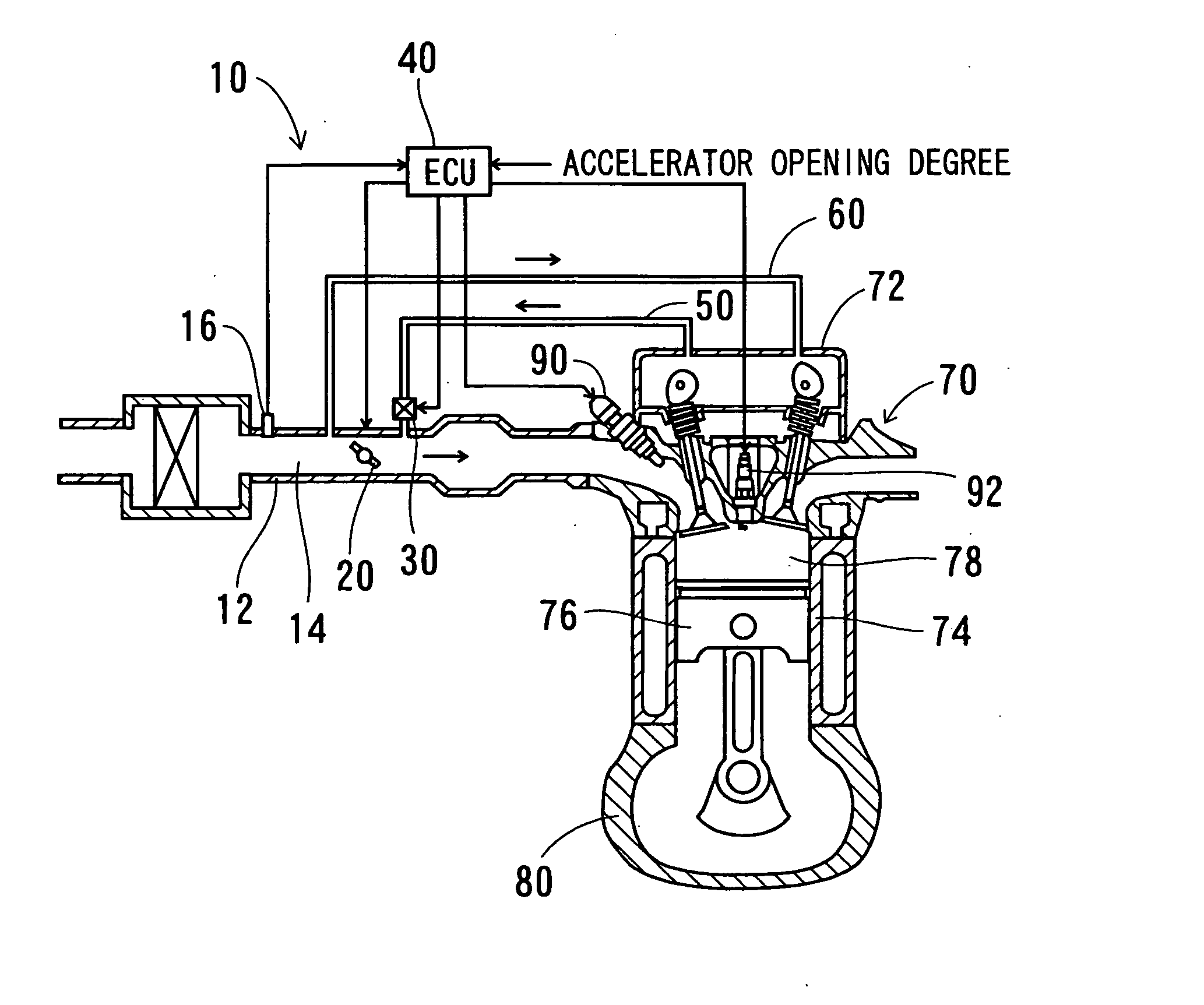
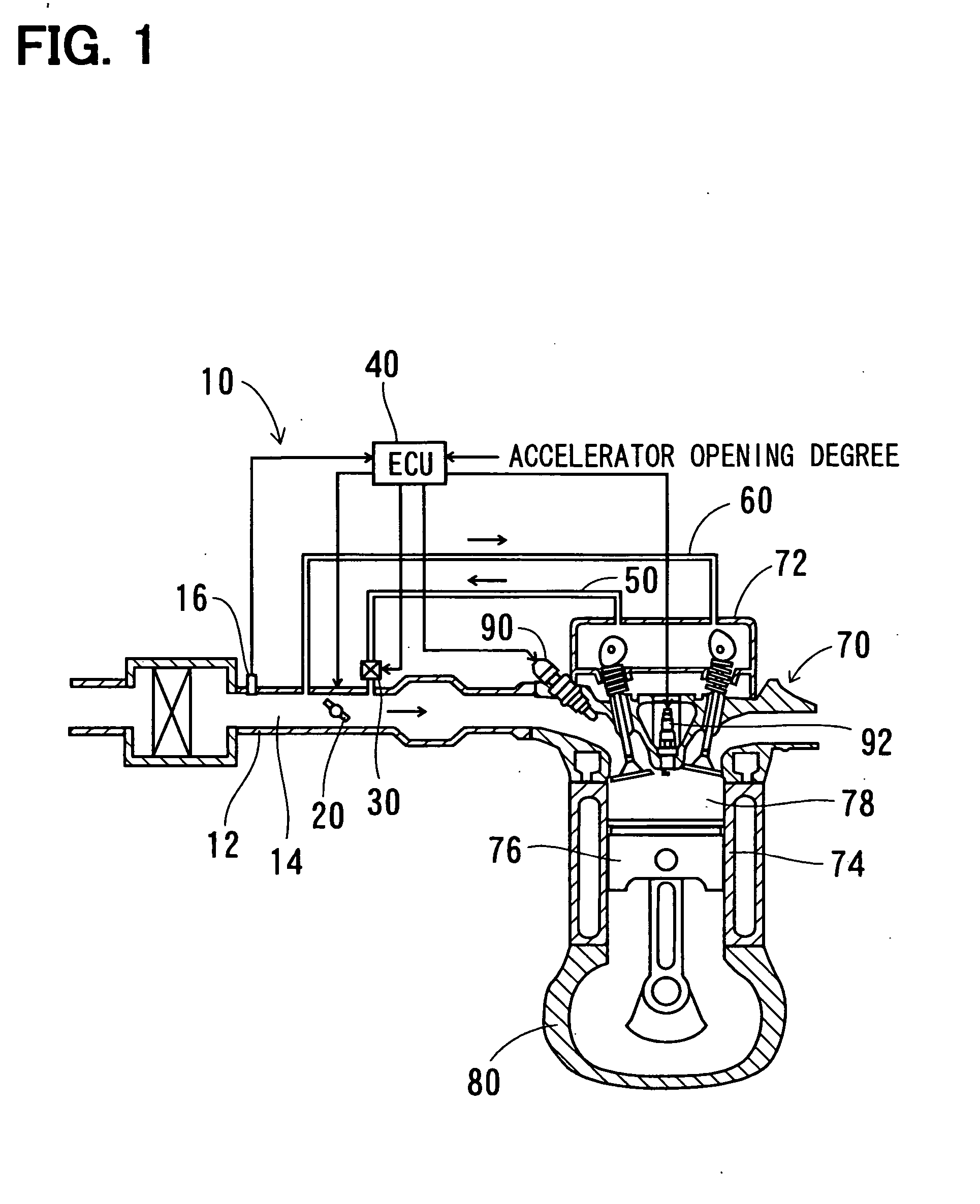
[0025]FIG. 1 shows a blow-by gas recirculation system 10 according to a first embodiment of the present invention. A flow sensor 16 is provided in an intake air pipe 12 to measure an intake air flow quantity (or simply referred to as an intake flow quantity) in an intake air passage 14, which is defined by the intake air pipe 12. As shown in FIG. 2, a throttle valve 20 is rotated by a motor 24 about an axis of a rotatable shaft 22.

[0026] A PV valve (a butterfly valve) 30, which serves as a flow quantity control valve, is arranged in an outflow passage 50. As shown in FIG. 2, the PCV valve 30 is rotated by the motor 24 about the axis of the shaft 22, which is shared with the throttle valve 20. As shown in FIG. 4A, the PCV valve 30 is installed to the shaft 22 in such a manner that an opening degree of the PCV valve 30 increases in proportional to an opening degree of the throttle valve 20. A flow quantity in the outflow passage 50 is controlled according to the opening degree of the...

second embodiment

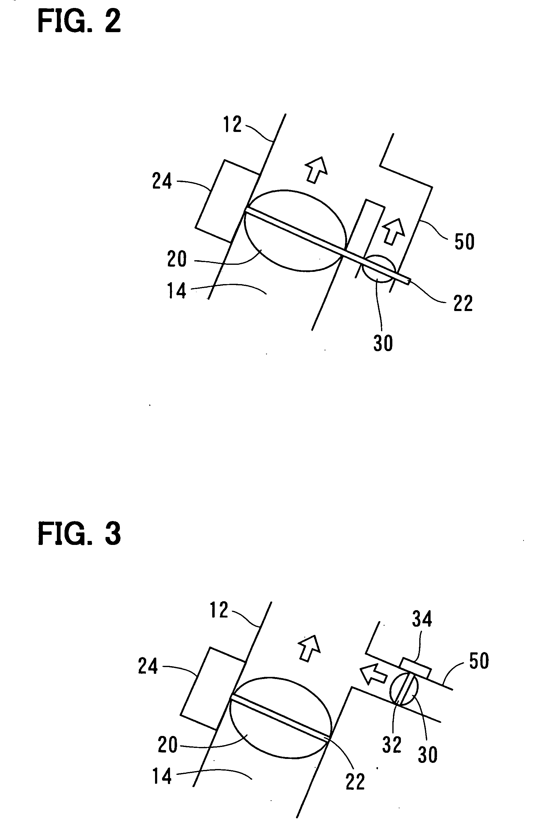
[0033] According to a second embodiment, as shown in FIG. 3, a rotatable shaft 32 of the PCV valve 30 is different from the rotatable shaft 22 of the throttle valve 20. Furthermore, the PCV valve 30 is rotated by a motor 34, which is different from the motor 24 of the throttle valve 20. The ECU 40 controls rotation of the motor 34 in such a manner that the opening degree of the PCV valve 30 increases in response to an increase in the opening degree of the throttle valve 20.

[0034] According to the second embodiment, the PCV valve 30 has the rotatable shaft 32, which is different from the rotatable shaft 22 of the throttle valve 20, and is rotated by the motor 34, which is different from the motor 24 of the throttle valve 20. Thus, as shown in FIGS. 4B-4F, the opening degree of the PCV valve 30 can be controlled in various ways with respect to the throttle opening degree, the intake air flow quantity or the load of the engine (or simply referred to as an engine load). Specifically, i...

third and fourth embodiments

[0035]FIG. 5 shows a third embodiment of the present invention, and FIG. 6 shows a fourth embodiment of the present invention. In the following description, components similar to those of the above embodiments will be indicated by the same numerals.

[0036] In a blow-by gas recirculation system 100 of the third embodiment shown in FIG. 5, a PCV valve 102, which serves as a flow quantity control valve, is a differential pressure regulating valve. A choke 62 is formed in the inflow passage 60, so that even though the passage cross sectional area of the outflow passage 50 and the passage cross sectional area of the inflow passage 60 are the same, a pressure loss of the outflow passage 50 is made smaller than a pressure loss of the inflow passage 60 at the time of fully opening the PCV valve 102. Thus, even in the case where the throttle opening degree is relatively large, and the negative pressure in the portion of the intake air passage 14, which is located on the downstream side of th...


PUM


Abstract

A PCV valve is arranged in an outflow passage. An ECU controls rotation of a motor such that an opening degree of the PCV valve increases in response to an increase in an opening degree of a throttle valve. The outflow passage connects an interior of a head cover of an engine to a portion of an intake air passage located on a downstream side of the throttle valve. The outflow passage recirculates blow-by gas leaked from a combustion chamber into an interior of a crankcase to the portion of the intake air passage located on the downstream side of the throttle valve. An inflow passage connects the interior of the head cover to a portion of the intake air passage located on an upstream side of the throttle valve. The inflow passage conducts intake air from the intake air passage to the interior of the head cover.

Description

CROSS REFERENCE TO RELATED APPLICATION [0001] This application is based on and incorporates herein by reference Japanese Patent Application No. 2005-283940 filed on Sep. 29, 2005. BACKGROUND OF THE INVENTION [0002] 1. Field of the Invention [0003] The present invention relates to a blow-by gas recirculation system that recirculates blow-by gas into an intake air passage in an internal combustion engine. [0004] 2. Description of Related Art [0005] In a previously proposed blow-by gas recirculation system (see, for example, Japanese Unexamined Patent Publication No. H06-229221), blow-by gas, which is leaked from a combustion chamber to an interior of a crankcase, is recirculated into a portion of an intake air passage, which is located on a downstream side of a throttle valve, by using a negative pressure generated in the intake air passage on the downstream side of the throttle valve. In this way, intake air is supplied from a portion of the intake air passage, which is located on an...

Claims


Application Information

Patent Timeline
Patent Type & Authority Applications(United States)
IPC IPC(8): F02B25/06
CPCF02M25/06Y02T10/121Y02T10/12
Inventor AMANO, NORIYASUITAKURA, HIDEAKIKATO, NAOYAHAYASHI, KAZUHIROUCHIYAMA, HIDETOSHI
Owner DENSO CORP
Why Eureka
Try Eureka