Antenna device used in radio-communications within short communication range and article container
an antenna device and radio communication technology, applied in the field of antennas and article containers, can solve the problems of low data readability, low operation efficiency of the above-described system, and the inability to read data from the rfid tag, etc., and achieve the effect of improving machine readability
- Summary
- Abstract
- Description
- Claims
- Application Information
AI Technical Summary
Benefits of technology
Problems solved by technology
Method used
Image

Examples
first embodiment
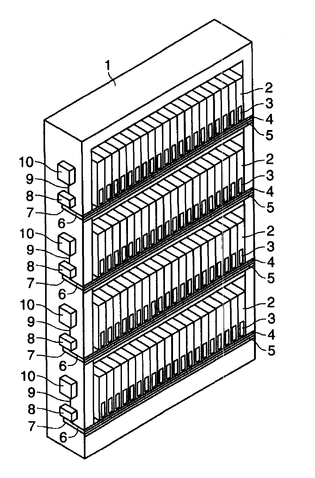
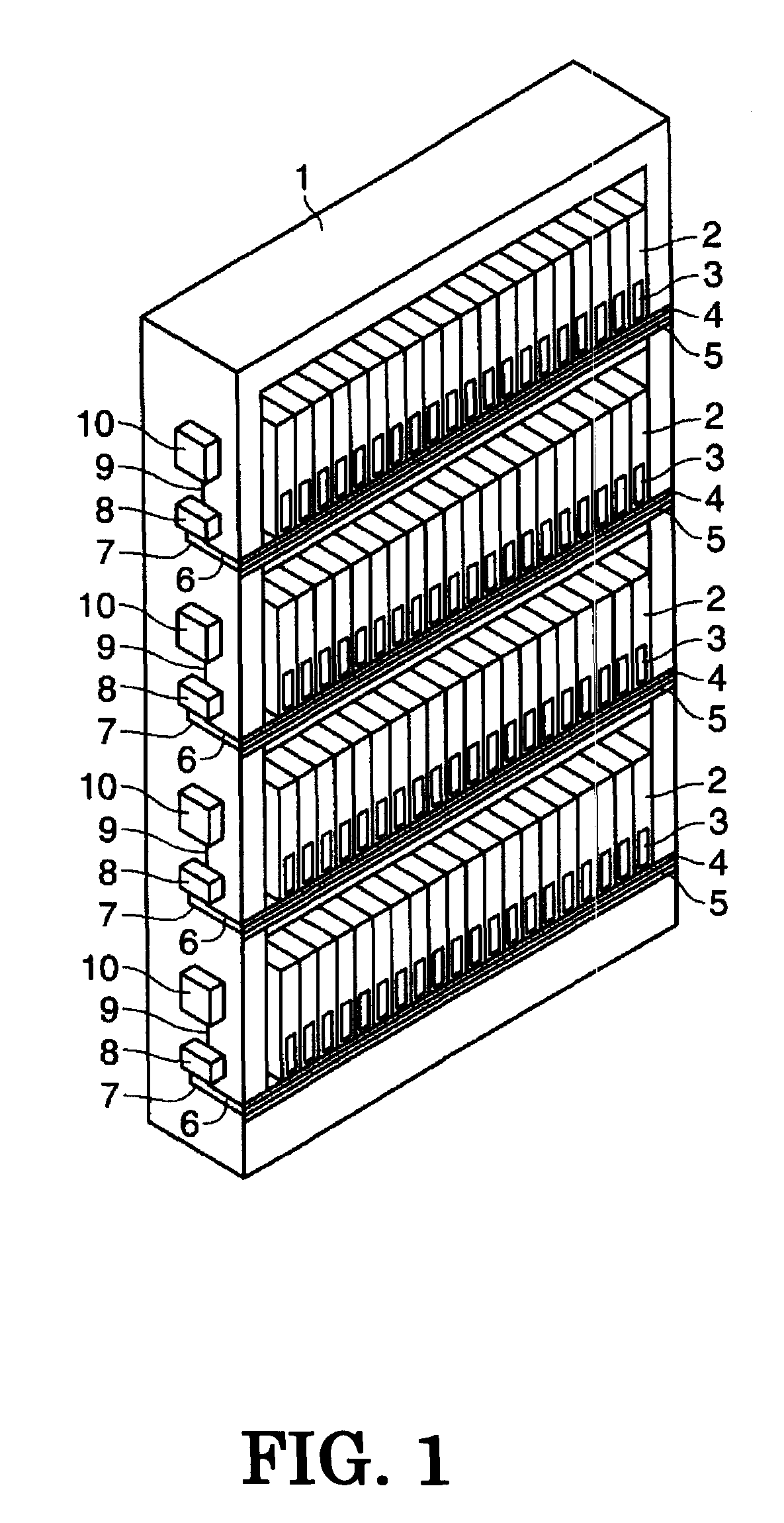
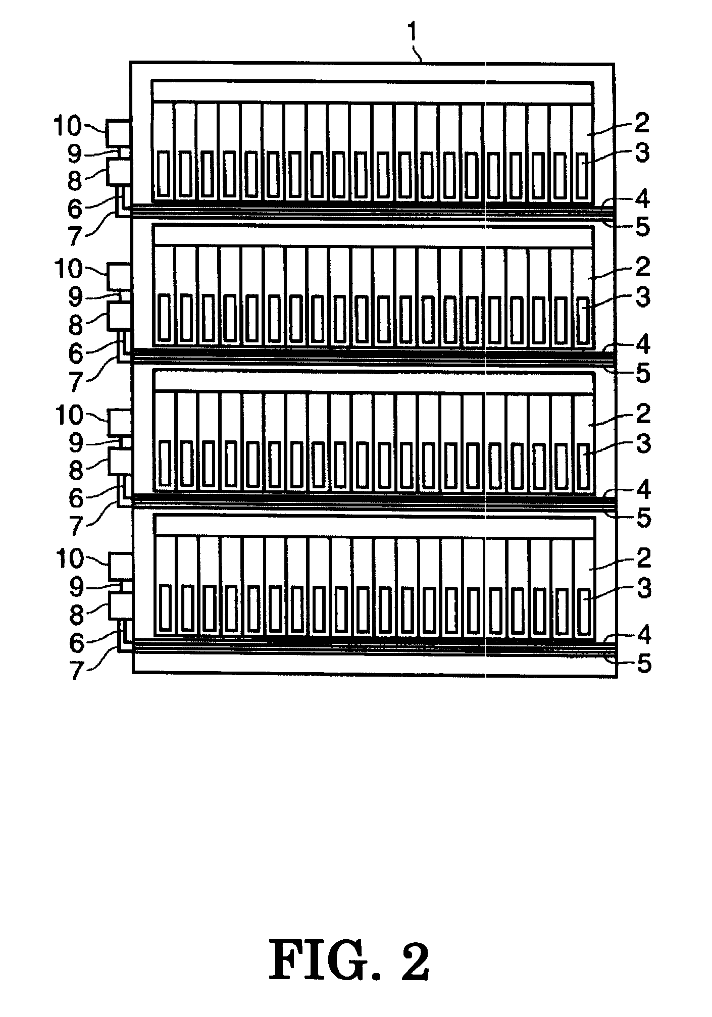
[0024]FIGS. 1 and 2 show an bookshelf 1, acting as an article container, which includes a radio-communication apparatus, an antenna device having first and second leakage transmission lines and a switch. Bookshelf 1 stores or displays a plurality of books (articles) 2, arranged thereon. An RFID tag 3, acting as a data carrier, is attached to each spine of the books. The article container includes bookshelves, showcases, supermarket shelves, boxes and so on, which display or house articles.
[0025] On front surface of each shelf portion of bookshelf 1 forming an article containing portion, a first and second leakage transmission lines 4 and 5 are arranged in parallel in a direction longitudinal to the each shelf portion. Each of the leakage transmission lines 4 and 5 is formed of a balanced line, e.g., feeder, in which two conductors are capable of being operated so that the voltages of the two conductors at any transverse plane are equal in magnitude and opposite in polarity with res...
second embodiment
[0033] In the second embodiment, modification of the second leakage transmission line is made, and other configurations except for the transmission line are the same as the first embodiment. Thus detailed description of other configurations is omitted. In place of the structure of the second leakage transmission line in which an end terminal of a balanced line is short-circuited, in this embodiment the balanced line includes an end terminal being opened and a length thereof is shorter than first leakage transmission line 4, as indicated in FIG. 4.
[0034] In detail, each of first and second transmission lines 4 and 51 defines start and end terminals and has a length, wherein the start terminals are mutually aligned, the first and second transmission lines 4 and 51 are arranged in parallel, and the length of second transmission line 51 is formed to be shorter than first transmission line 4 by a difference (L). In other words, first and second transmission lines 4 and 51 are formed inc...
third embodiment
[0037] Referring to FIGS. 5 and 6, third embodiment will now be described. A bookshelf 1 has a plurality of shelve portions. An RFID tag reader 10 is mounted on a side surface of bookshelf 1, corresponding to each shelf portion. A switch 8 is mounted on the other side surface of bookshelf 1, corresponding to each shelf portion. A third leakage transmission line 12 composed of a balanced line is arranged on a front surface of the respective shelves in a direction longitudinal to the shelf.
[0038] One terminal of third transmission line 12 is connected with RFID tag reader 10 via a cable 13, and the other terminal thereof is connected with switch 8 via a cable 14, wherein cables 13 and 14 are, for example, coaxial cables. First and second transmission lines 42 and 52, each of which is composed of a balanced line, are respectively connected with switch 8.
[0039] Referring to FIG. 6, first and second transmission lines 42 and 52 are formed in parallel such that both end terminals thereo...
PUM
 Abstract
Description
Claims
Application Information
 - R&D
- Intellectual Property
- Life Sciences
- Materials
- Tech Scout
- Unparalleled Data Quality
- Higher Quality Content
- 60% Fewer Hallucinations
Browse by: Latest US Patents, China's latest patents, Technical Efficacy Thesaurus, Application Domain, Technology Topic, Popular Technical Reports.
© 2025 PatSnap. All rights reserved.Legal|Privacy policy|Modern Slavery Act Transparency Statement|Sitemap|About US| Contact US: help@patsnap.com