Projection display apparatus and three-plate type of liquid crystal projector using the same

a technology of projection display and liquid crystal projector, which is applied in the direction of instruments, color television details, optics, etc., can solve the problems of deteriorating image quality, affecting the quality of images, and unable to achieve the optimal alignment conditions for producing those two states, and achieves the effect of higher contras

Inactive Publication Date: 2007-04-05
VICTOR CO OF JAPAN LTD
View PDF6 Cites 23 Cited by
  • Summary
  • Abstract
  • Description
  • Claims
  • Application Information

AI Technical Summary

Benefits of technology

[0016] The present invention has been made in consideration of the foregoing difficulties, and an object of the present invention is to provide a projection display apparatus capable of image of higher contrast by giving optimum conditions to alignment of liquid crystal and a phase compensator. Another object of the present invention is to provide reasonable application conditions in employing the foregoing projection display apparatus in a three-plate type of liquid crystal projector.
[0019] In this case, however, in a case where a pre-tilt angle is given to the liquid crystal molecules, the maximum output in the bright state is limited to four conditions consisting of 45, 135, 225 and 315 degrees as azimuthal angles made from a reference line directed in the direction of incident polarized light. The fact that high brightness was obtained in those conditions was confirmed actually from an experimental viewpoint. In particular, among those four conditions of the azimuthal angle, the alignment conditions on azimuthal angles 225 and 315 degrees are greater than the other angles in terms of further improving the contrast. That is, there is no difference in the brightness among the four azimuthal angle conditions in the bright state, but there is a comparatively large difference in the lower level in the dark state. These facts have been confirmed by the inventors. Additionally, when comparing the liquid-crystal alignment conditions in the case of 45 and 135 degrees and in the case of 225 and 315 degrees, the latter conditions on 225 and 315 degrees are superior to the former in terms of the contrast within a range of ±3 degrees.

Problems solved by technology

However, in the perpendicularly aligned state, some molecules closely positioned to alignment membranes on the respective substrates are still kept at alignment angles which are close to the horizon, thus deteriorating a black level due to retardation to be caused (i.e., the contrast is obliged to be lowered).
That is, the liquid crystal molecules fall down in different various directions by responding to the voltage application, bringing about disclination which deteriorates image quality.
However, optimum alignment conditions for producing those two states have been unknown yet.

Method used


Image

  • Projection display apparatus and three-plate type of liquid crystal projector using the same
  • Projection display apparatus and three-plate type of liquid crystal projector using the same
  • Projection display apparatus and three-plate type of liquid crystal projector using the same

Examples


first embodiment

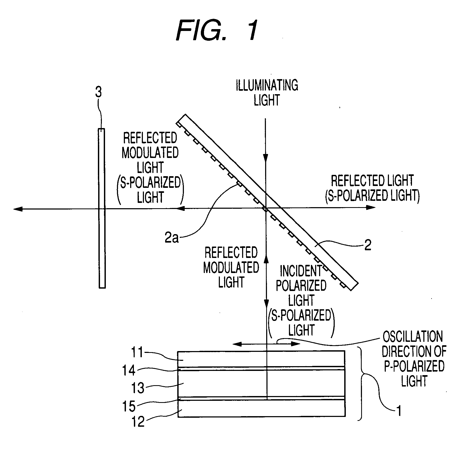
[0035] Referring to FIGS. 1-4, a first embodiment will now be described.

[0036]FIG. 1 shows the essential configuration of a projection display apparatus 100 that serves as a processor for a single-color optical system, the processor composing part of a three-plate type of liquid crystal projector (not shown in FIG. 1) which employs a reflective liquid crystal display device according to the present invention.

[0037] As shown in FIG. 1, the projection display apparatus 100 is provided with a reflective liquid crystal display device 1 as stated above, a WG-PBS (wire grid type of polarizing beam splitter) 2, and an analyzer 3 composed of for example a polarization plate.

[0038] Of these, the WG-PBS 2 is arranged obliquely at an oblique angle of 45 degrees. The analyzer 3 detects modulated light reflected from the WG-PBS 2. The WG-PBS 2 has a wire grid (WG) 2a which keeps parallelism with the reflective liquid crystal display device 1, so that illuminating light entering the WG-PBS 2 i...

second embodiment

[0050] Referring to FIGS. 5 to 8, a second embodiment of the present invention will now be described.

[0051] In the configurations of the second embodiment and subsequent embodiments, the similar or identical components to those in the first embodiment will be given the same reference numerals as those given in the first embodiment and their explanations are simplified or omitted for the sake of simplified explanations.

[0052] The second embodiment relates especially to an improvement in contrast due to retardation caused in the plane direction of the liquid crystal layer 13.

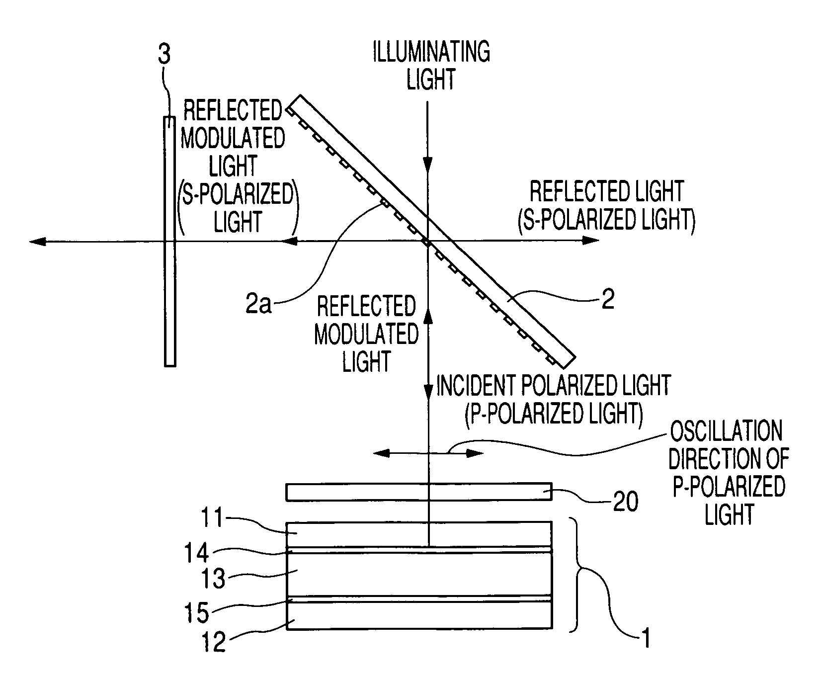
[0053] As shown in FIG. 5, a projection display apparatus according to the second embodiment is provided, as part of its essential configuration, a phase compensator 20, which is composed of a phase compensating plate, is placed to intervene between the reflective liquid crystal display device 1 and the WG-PBS 2. The intervening phase compensator 20 aims at preventing contrast from being lowered, which is cause...

third embodiment

[0063] Referring to FIGS. 9 to 12, a second embodiment of the present invention will now be described.

[0064] The third embodiment relates to a three-plate type of liquid crystal projector capable of displaying color images with contrast as high as possible by adopting the projection display apparatus described in either the first or second embodiment.

[0065] The essential configuration of this three-plate type of liquid crystal projector is basically the same as that shown in FIG. 9, except for configurations necessary for composing colors. Such color-composing configurations include a color composing prism 40 having three planes serving as incident planes. To be opposed to the three incident planes, projection display apparatuses 10R, 10G and 10B are arranged, respectively, each of which function as a processor processing each of single-color light beams of red (R), green (G) and blue (B). Inside the color composing prism 40, there are provided an optical multiple layer 40r allowi...


PUM

PropertyMeasurementUnit
angleaaaaaaaaaa
phase angleaaaaaaaaaa
azimuthal anglesaaaaaaaaaa

Abstract

A projection display apparatus comprises a reflective LC display device and a polarizing beam splitter having a polarizing separative plane and wired grids. The LC molecules of the device are aligned such that i) a segment on a second subtracted, produced by projecting a major axis of each LC molecule perpendicularly onto the second substrate, makes an angle of 42 to 48 degrees counterclockwise or counterclockwise in relation to a direction of a straight line on the second substrate, formed by projecting each wire grid perpendicularly onto the second substrate and ii) of both ends of the segment, one end meeting an end of each LC molecule, which is positioned nearer to the second substrate than the other end, is positioned nearer to an intersection at which a plane including the polarizing separative plane and a plane including the second substrate mutually intersects, than the other end of the segment.

Description

CROSS REFERENCE TO RELATED APPLICATION [0001] The present application relates to and incorporates by reference Japanese Patent application No. 2005-289476 filed on Oct. 3, 2005. BACKGROUND OF THE INVENTION [0002] 1. Field of the Invention [0003] The present invention relates to a projection display apparatus equipped with reflective liquid crystal (LC) display devices and a three-plate type of liquid crystal projector that uses the projection display apparatus as for modulating each monochromatic light. [0004] 2. Description of the Related Art [0005] In recent years, liquid crystal projectors have been incorporated into popular tools that can be used as large-sized screen display apparatuses. Such display apparatuses, which can be used for various things, such as meetings with screen presentation, home theaters, and other uses, have been developed on various types of display techniques. [0006] In particular, a projection display apparatus which processes respective monochromatic lig...

Claims


Application Information

Patent Timeline
Patent Type & Authority Applications(United States)
IPC IPC(8): G02F1/1335
CPCG02F1/133536G02F1/133553G02F1/1393G02F2001/133531H04N9/3167G02F1/133531
Inventor SHIMIZU, SHIGEOMUKOUYAMA, TATSUYA
Owner VICTOR CO OF JAPAN LTD
Why Eureka
Try Eureka