Electrical contactor current sensing system and method

a current sensing and contactor technology, applied in the direction of relays, protective switch details, emergency protective arrangements for limiting excess voltage/current, etc., can solve the problems of reducing the flexibility of offering to the user devices with and without current sensing capabilities, adding significantly to the cost of base units

Active Publication Date: 2007-04-05
ROCKWELL AUTOMATION TECH
View PDF13 Cites 17 Cited by
  • Summary
  • Abstract
  • Description
  • Claims
  • Application Information

AI Technical Summary

Problems solved by technology

For example, certain protective circuitry, such as fuses and thermal overload circuits, simply react to heating that results from high or excessive currents through the devices and conductors.
However, such integration of current sensors can add significantly to a cost of the base units, and reduces the flexibility of offering to the user devices with and without current sensing capabilities.

Method used


Image

  • Electrical contactor current sensing system and method
  • Electrical contactor current sensing system and method
  • Electrical contactor current sensing system and method

Examples


Embodiment Construction

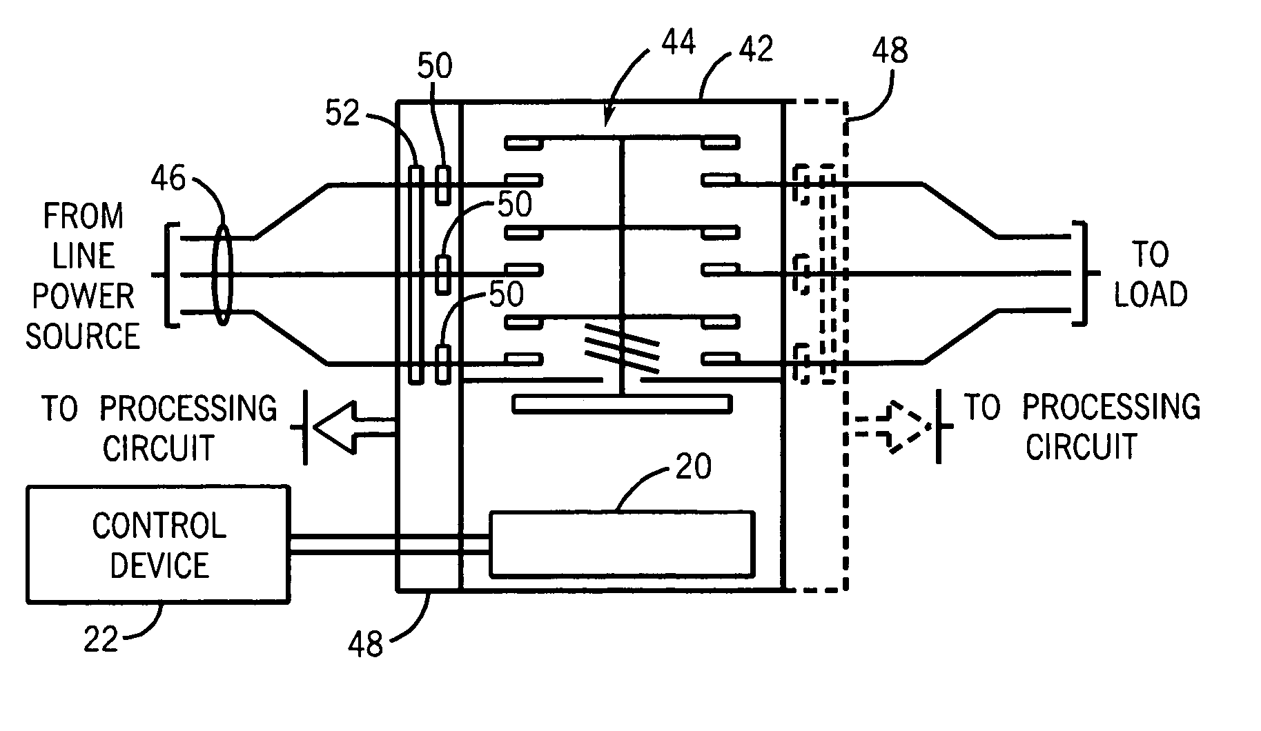
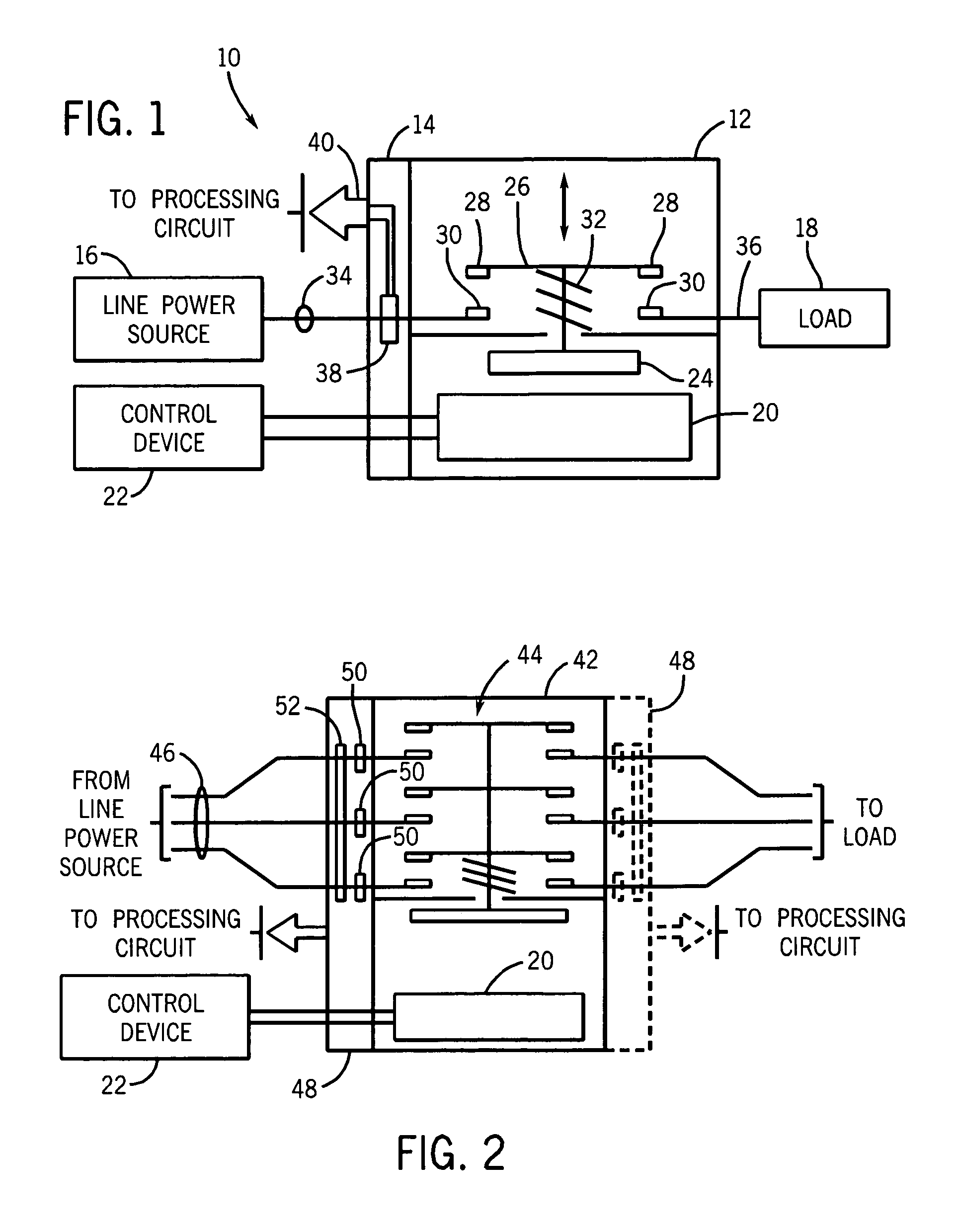
[0011] Turning now to the drawings, and referring first to FIG. 1, a current sensing contactor 10 is illustrated generally as including a contactor 12 and a current sensing module 14. The contactor is electrically coupled between a line power source 16 and a load 18. As will be appreciated by those skilled in the art, many such applications exist for such contactors, and the present invention is not intended to be limited to any particular application. For example, the line power source 16 may include a direct connection to a power grid, or may be a dc source such as a battery. Moreover, the line power source 16 may include circuitry for conditioning signals applied to the contactor, such as various power conversion circuits, inverter circuits, and so forth. Also, the line power source 16 will typically include, in an actual application, a range of additional components, such as fuses, circuit breakers, thermal overloads, safety contactors, and so forth. Similarly, load 18 may inclu...


PUM


Abstract

A current sensing module is provided for contactors and similar switch gear. The current sensing module is packaged so as to be capable of mounting on a line or a load side of a contactor. The current sensing module may be eliminated where current signals are not needed, but can be added to the package where monitoring and control functions may benefit from sensed current signals on either or both sides of a contactor. The current sensing module may be configured as a single or multiple-phase device, and may output either analog or digital signals to local devices or to networked devices.

Description

BACKGROUND [0001] The present invention relates generally to switch gear and, more particularly, to a technique for obtaining current signals through power-conveying conductors routed to or from switch gear in a modular fashion. [0002] A host of applications exist for switch gear for delivering electric power between a source and a load. In general, such switch gear includes contactors and relays of various types. The switch gear is generally placed in series with various other components, typically downstream of circuit protective components, such as fuses and circuit breakers, and upstream of components that apply the controlled power to a load. Such switch gear is used throughout industry, and in all commercial, mining, marine, and even consumer settings. In many applications, the switch gear is used to provide power for electric motors, although such loads are certainly not the only application of such switch gear. [0003] Certain applications do or could benefit from enhanced co...

Claims


Application Information

Patent Timeline
Patent Type & Authority Applications(United States)
IPC IPC(8): H02H7/08
CPCH01H50/021H01H50/045H01H71/123H01H83/02H01H83/14H02H3/347
Inventor BATTANI, JEFFERY JOHNLEE, PING SOON
Owner ROCKWELL AUTOMATION TECH
Why Eureka
Try Eureka