Vehicle control system

a control system and vehicle technology, applied in the field of vehicle control systems, can solve the problems of increasing system costs, affecting and being unable to continue monitoring for failed nodes in the system, so as to improve the development efficiency of control application software and reduce costs

Active Publication Date: 2007-04-05
HITACHI LTD
View PDF2 Cites 71 Cited by
  • Summary
  • Abstract
  • Description
  • Claims
  • Application Information

AI Technical Summary

Benefits of technology

[0005] The present invention has been made in view of the above circumstances and has an object to provide a vehicle control system which can identify any failed node in a network accurately without installing a special system-monitoring node.
[0009] The present invention allows determinations such as described above to be made using a system composed of typical ECUs without the need to install a master node (server) which centrally controls node status determination of all nodes or a node (shared disk) which holds data to be shared. Thus, it makes it possible to identify any failed node accurately at low costs.
[0010] The present invention also makes it possible to check for faults which cannot be detected by network trouble shooting alone, including abnormal software processes (including failures in upper layers of the data link layer) which can occur even when communication are conducted normally.
[0011] When implementing such a failed-node monitoring function using middleware, a control application can acquire node status information using a predetermined AP1 (Application Program Interface), and thus it is possible to improve development efficiency of control application software.

Problems solved by technology

If the shared disk fails, it becomes impossible to continue monitoring for failed nodes in the system.
Besides, the use of the shared disk may add to system costs.

Method used


Image

  • Vehicle control system
  • Vehicle control system
  • Vehicle control system

Examples


example 1

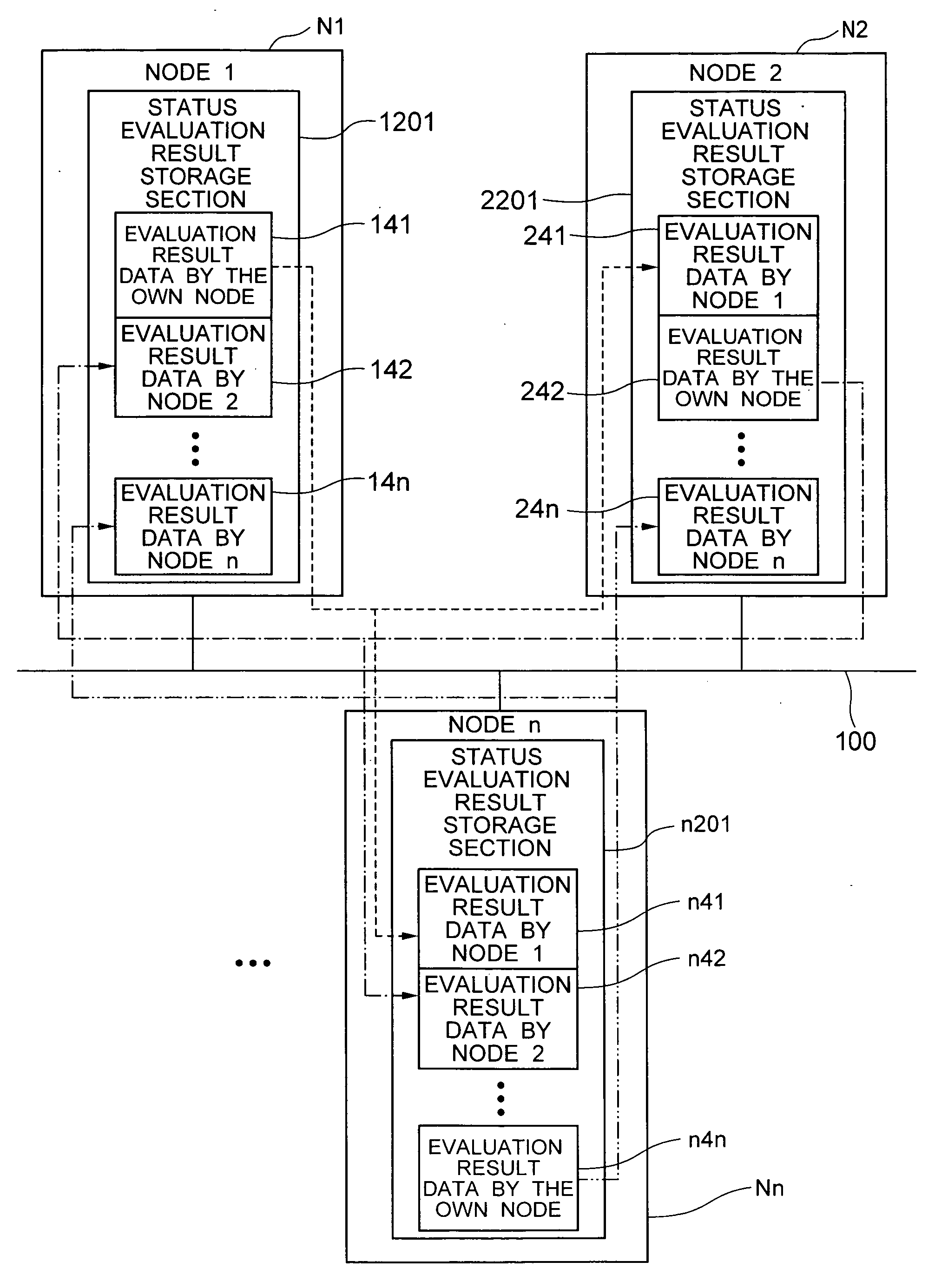
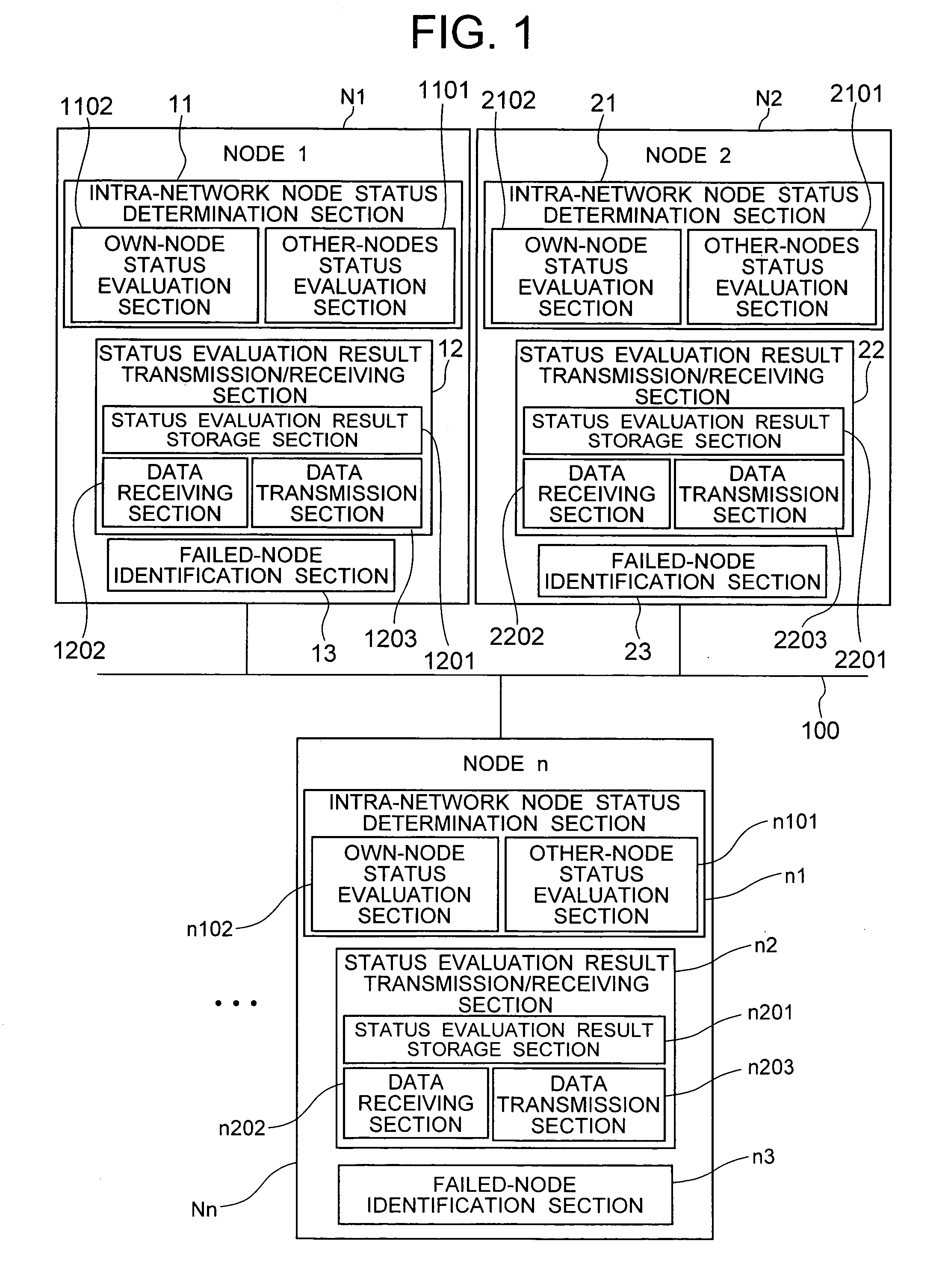
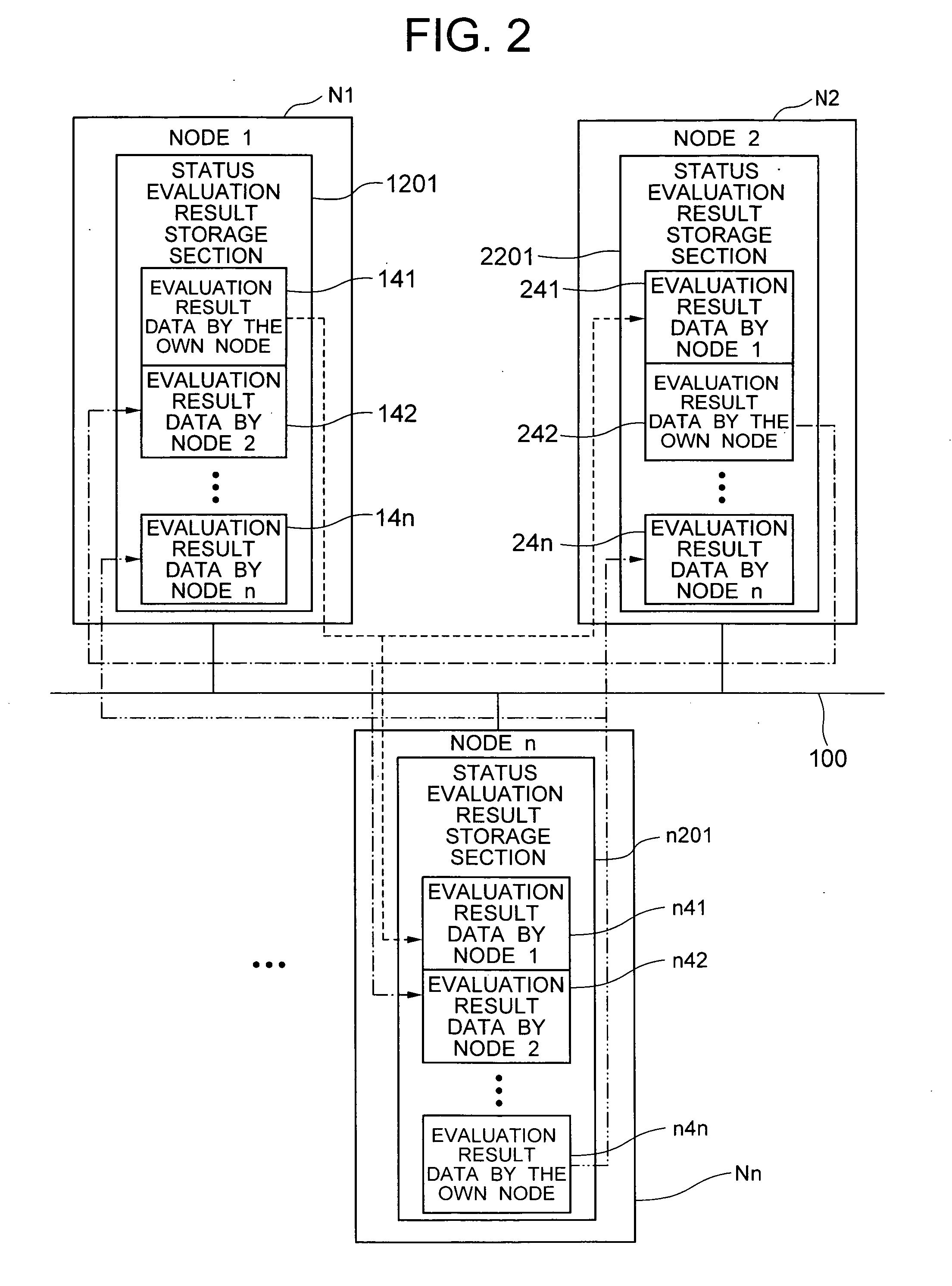
[0062] First, a basic configuration of the vehicle control system according to the present invention will be described with reference to FIGS. 1 to 4. As shown in FIG. 1, the vehicle control system according to the present invention consists of multiple nodes—namely, node 1 (N1), node 2 (N2), . . . , node n (Nn)—which are connected via a network 100. The nodes are processing units connected to a network and capable of communicating information via the network. Specifically, they include various electronic control units, actuator drivers, and sensors mounted on a vehicle. The network 100 is a communication network capable of multiplex communication as well as broadcasting which involves transmitting the same content simultaneously from a node to all the other nodes connected to the network.

[0063] Each node, Ni, N2, . . . , or Nn (hereinafter referred to as Nx) has a node status determination section x1 (11, 21, . . . , or n1), status evaluation result transmitting / receiving section ...

example 2

[0128] Next, description will be given of an example in which the node status determination according to the present invention is applied to a vehicle control system.

[0129]FIG. 23 shows an example of a vehicle control system. According to this example, a vehicle 1 is equipped with steering and brake backup mechanisms, but the same configuration may be used for vehicles which are not equipped with steering and brake backup mechanisms.

[0130] A vehicle control system 901 according to this example is equipped with an integrated vehicle motion control ECU 910 which centrally controls vehicle motion based on signals from a steering angle sensor Sen1 which measures a rotation angle of a steering wheel 951, brake pedal position sensor Sen2 which measures a depression of a brake pedal 952, accelerator pedal position sensor Sen3 which measures a depression of an accelerator pedal, and sensors (e.g., an acceleration sensor, yaw rate sensor, and wheel speed sensor: not shown) which detect veh...

example 4

[0169] In the above examples, all the nodes on the network identifies (ID process) any failed node among all the other nodes on the network or all the other nodes in the group based on their own status decisions.

[0170] In addition to this highly reliable technique, it is also possible to share the ID process with the other nodes on the network or the other nodes in the group to further reduce the CPU processing load. Specifically, in a group of n nodes (including a case in which all the nodes in a network belongs to a single group), one node performs the ID process of only m nodes (n>m>1) and transmits results to the other nodes and receives ID results of the remaining nodes from the other nodes. Hereinafter this technique is referred to as a “decision broadcasting method.” Incidentally, this method become the same as the above example when m=n.

[0171]FIG. 35 is a flowchart showing how to implement a node status (failed-node) monitoring function by the decision broadcasting method....


PUM


Abstract

In a vehicle control system in which a large number of ECUs operate in coordination via a network, each node has an intra-network node status determination section, other node's status decision transmitting / other nodes status decision receiving section, and failed-node identification section. The nodes exchange decisions made by the intra-network node status evaluation section with other nodes and thereby identify failed node.

Description

BACKGROUND OF THE INVENTION [0001] The present invention relates to a vehicle control system in which a plurality of electronic control units are connected via a network. [0002] Recently, vehicle control systems which reflect accelerator pedal, steering wheel, braking pedal, and other operations performed by a driver in driving force, steering force, and braking force generating mechanisms by means of electronic control rather than mechanical coupling have been developed actively to improve driving comfort and safety. In such a system, a plurality of electronic control units (ECU) distributed over the vehicle perform coordinated operation by exchanging data via a network. When an ECU within the network develops a fault, it is essential for fail-safe purposes that the remaining normal ECUs identify the faulty ECU accurately and perform appropriate backup control depending on the faulty spot. Incidentally, ECUs connected to a network may be referred to as nodes hereinafter. [0003] To ...

Claims


Application Information

Patent Timeline
Patent Type & Authority Applications(United States)
IPC IPC(8): H04J3/14B60R16/02B60R16/023G08G1/09G08G1/16
CPCB60W50/0205
Inventor SAKURAI, KOHEIMORITA, YUICHIROHOSHINO, MASATOSHITAKAHASHI, YOSHIAKIKUROSAWA, KENICHIMATSUBARA, MASAHIRO
Owner HITACHI LTD
Why Eureka
Try Eureka