Active noise-reduction control apparatus and method

a control apparatus and noise reduction technology, applied in the field of active noise reduction, can solve the problems of destabilization of control, large time requirement for amplitude convergence, and degradation of control effect, and achieve the effect of reducing white noise, reducing white noise, and reducing the noise of snoring

Inactive Publication Date: 2007-04-05
KK TOSHIBA
View PDF4 Cites 179 Cited by
  • Summary
  • Abstract
  • Description
  • Claims
  • Application Information

AI Technical Summary

Benefits of technology

[0044]FIG. 23 is a view illustrating a system structure for performing experiments for verifying the advantage of the apparatus of FIG. 21;
[0045]FIG. 24A is a graph illustrating the effect of reducing white noise by a first error microphone;
[0046]FIG. 24B is a graph illustrating the effect of reducing white noise by a second error microphone;
[0047]FIG. 25A is a graph illustrating the effect of reducing the noise of snoring by the first error microphone;
[0048]FIG. 25B is a graph illustrating the effect of reducing the noise of snoring by the second error microphone; and
[0049]FIG. 26 is a view illustrating the effect of reducing the noise of snoring by the first and second error microphones in units of frequency bands.

Problems solved by technology

In active control, when a Filtered-X least mean square (LMS) algorithm as a generally used arithmetic algorithm is used, noise that greatly fluctuates in sound pressure level, or error factors in the varying acoustic path of a moving sound source may lead to degradation of control effect, whereby the control is inevitably destabilized.
However, it has a fatal problem that a lot of time is required for amplitude convergence.
Because of this problem, the LMS algorithm is hard to apply to level-varying noise or moving noise.
Since the same gradient-type LMS algorithm as the conventional Filtered-X algorithm is used for updating the coefficients, the convergence speed cannot be improved, either.
However, even the direct FTF method exhibits instability when it is used to process an unsteady sound that significantly varies in level, therefore cannot easily follow it.

Method used


Image

  • Active noise-reduction control apparatus and method
  • Active noise-reduction control apparatus and method
  • Active noise-reduction control apparatus and method

Examples


first embodiment

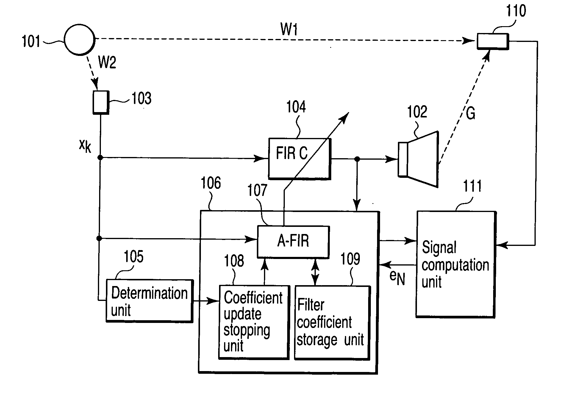
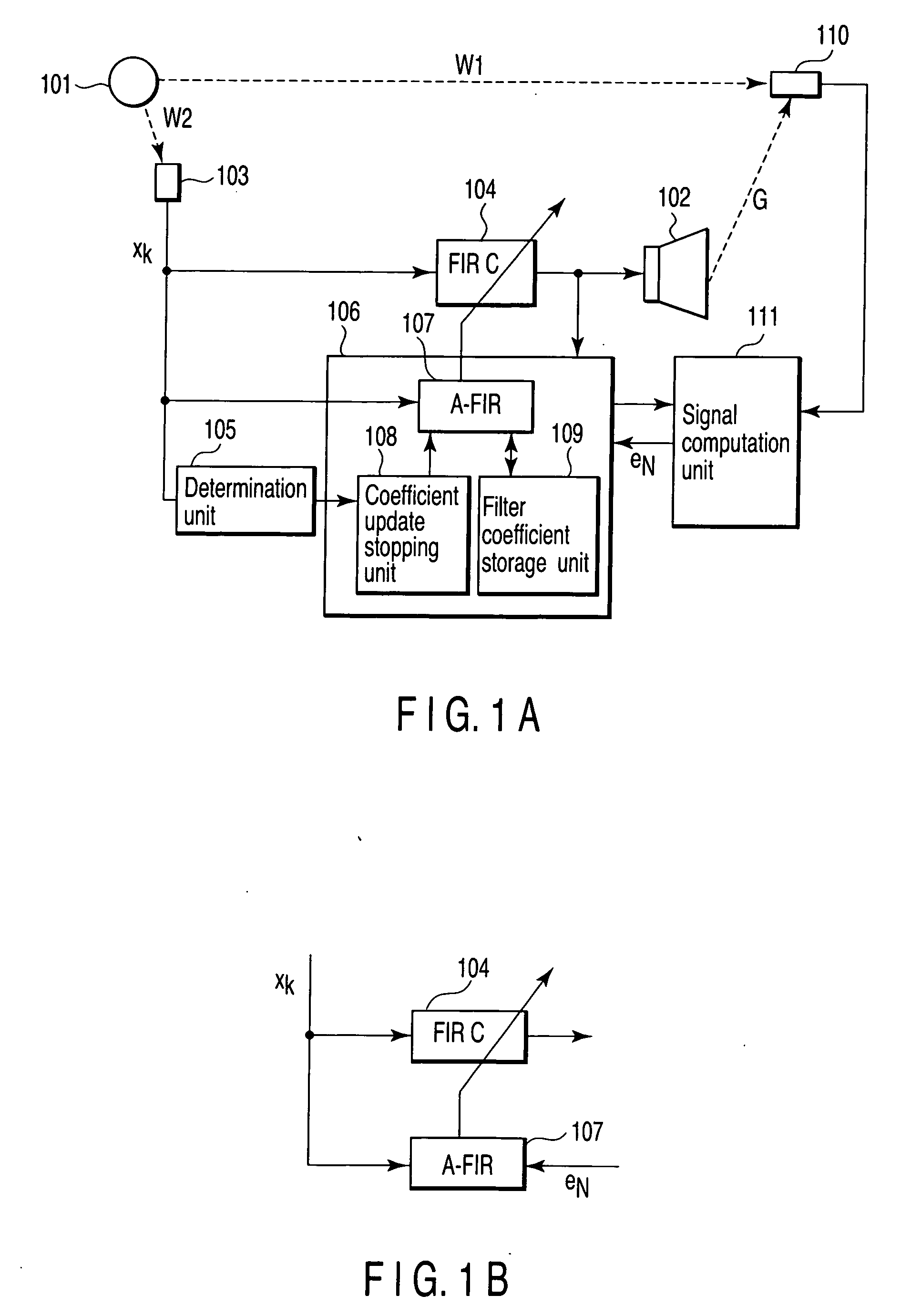
[0054] Referring to FIG. 1A, an active noise-reduction control apparatus according to a first embodiment of the invention will be described.

[0055] The active noise-reduction control apparatus of the first embodiment comprises a control-sound source unit 102, reference signal generator 103, digital filter arithmetic unit 104, determination unit 105, filter coefficient updating unit 106, error microphone 110 and signal computation unit 111. The filter coefficient updating unit 106 includes an adaptive filter unit 107, coefficient update stopping unit 108 and filter coefficient storage unit 109. The active noise-reduction control apparatus of the first embodiment is used to reduce a to-be-reduced noise (target noise) 101 emitted from a sound source.

[0056] The reference signal generator 103 receives the target noise 101, generates a reference signal based on the target noise 101, and supplies the reference signal to the digital filter arithmetic unit 104, determination unit 105 and fi...

second embodiment

[0096] Referring to FIG. 7, an active noise-reduction control apparatus according to a second embodiment of the invention will now be described.

[0097] The active noise-reduction control apparatus of the second embodiment differs from that of the first embodiment only in the internal structure of the filter coefficient update unit 106. The filter coefficient update unit 106 of the second embodiment comprises an adaptive filter unit 107 and coefficient initialization unit 701.

[0098] The coefficient initialization unit 701 initializes the coefficient of the digital filter arithmetic unit 104 when a change in the level of the reference signal output from the reference signal generator 103 falls outside the threshold value range. Namely, in the case of, for example, such a general adaptive filter as shown in FIG. 1B, the coefficient C of the control filter is once initialized to zero. See, for example, the above-mentioned equation (Eq. 1).

[0099] As described above, the second embodime...

third embodiment

[0111] Referring to FIG. 17, an active noise-reduction control apparatus according to a third embodiment of the invention will be described.

[0112] The active noise-reduction control apparatus of the third embodiment differs from that of the first embodiment only in the internal structure of the filter coefficient update unit 106. The filter coefficient update unit 106 of the third embodiment comprises a filter coefficient adjustment unit 1701 and estimated-error computation unit 1702.

[0113] The estimated-error computation unit 1702 computes an estimated error EE based on a reference signal from the reference signal generator 103 and an error signal from the error microphone 110. The estimated error EE is expressed by

EE=10 log10(Σe2 / Σd2)   (Eq. 5)

where e is an error microphone signal, and d is a reference microphone signal.

[0114] The filter coefficient adjustment unit 1701 adjusts the prestored coefficient of the adaptive filter unit 107 based on the estimated error EE. As a re...


PUM


Abstract

Apparatus includes generator generating reference signal based on noise emitted from sound source, detector detecting level of reference signal and change in level, unit comparing change with threshold-value range and produce compared result, filter filtering reference signal, adaptive filter having variable filter coefficient, unit updating filter coefficient according to change of level of reference signal for obtaining an updated filter coefficient, unit stopping updating of filter coefficient in response to compared result when change falls outside threshold-value range, unit storing updated filter coefficient each time filter coefficient is updated, generator generating control signal using stored filter coefficient, unit generating control sound based on control signal, microphone detecting synthesis sound pressure of control sound and noise to produce an error signal, and unit setting stored filter coefficient to more accurate coefficient than stored filter coefficient based on error signal, and signal acquired by filtering control signal through filter.

Description

CROSS-REFERENCE TO RELATED APPLICATIONS [0001] This application is based upon and claims the benefit of priority from prior Japanese Patent Application No. 2005-282804, filed Sep. 28, 2005, the entire contents of which are incorporated herein by reference. BACKGROUND OF THE INVENTION [0002] 1. Field of the Invention [0003] The present invention relates to active noise reduction for reducing, using reference signal supply means, an error microphone and control speaker, the level of a noise source, such as an unsteady sound having a varying sound pressure level, an intermittent sound including silent portions and emitted by a sound source that intermittently stops, or a sound emitted from a moving sound source. More particularly, it relates to a control method and apparatus for suppressing sound pressure at the position of an error microphone. [0004] 2. Description of the Related Art [0005] In active control, when a Filtered-X least mean square (LMS) algorithm as a generally used arit...

Claims


Application Information

Patent Timeline
Patent Type & Authority Applications(United States)
IPC IPC(8): A61F11/06G10K11/16H03B29/00
CPCG10K11/1788G10K2210/3028G10K11/17854G10K11/17835G10K11/17823G10K11/17881
Inventor HOSAKA, RIKAENAMITO, AKIHIKOKOJIMA, KENJIKIJIMOTO, SHINYA
Owner KK TOSHIBA
Why Eureka
Try Eureka