

Ring seal system with reduced cooling requirements
- Summary
- Abstract
- Description
- Claims
- Application Information
AI Technical Summary
Benefits of technology
Problems solved by technology
Method used
Image

Examples
Embodiment Construction
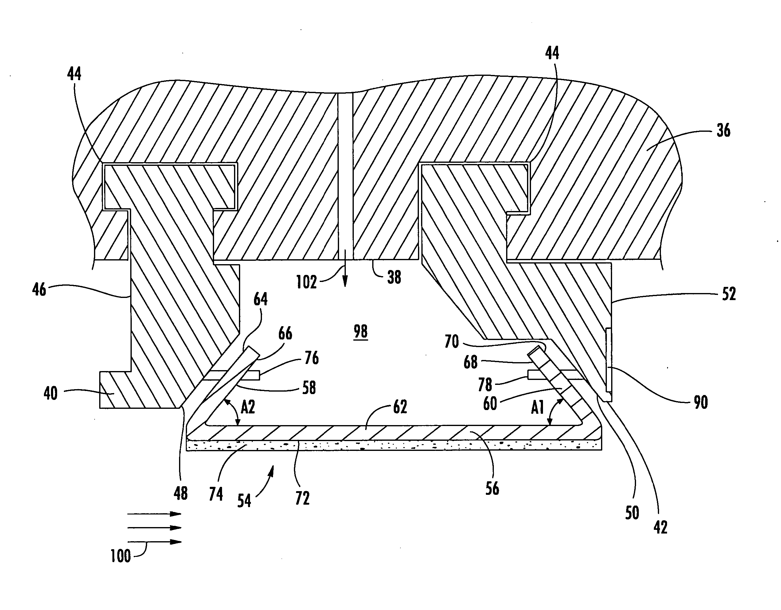
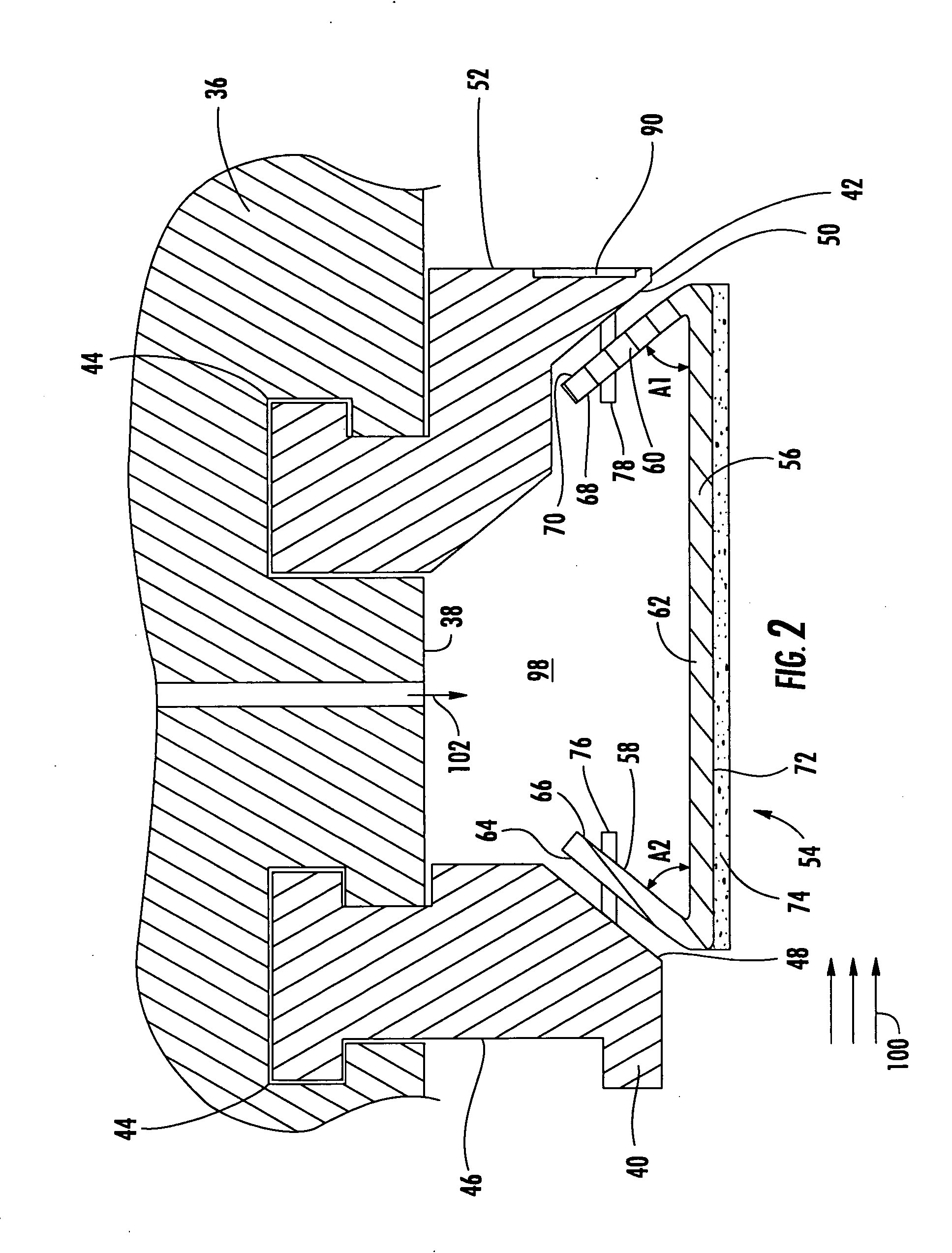
[0036] Embodiments of the invention are directed to systems for minimizing the amount of air dedicated to cooling a ring seal in the turbine section of a turbine engine. Aspects of the invention will be explained in connection with various ring seal systems, but the detailed description is intended only as exemplary. Embodiments of the invention are shown in FIGS. 2-21, but the present invention is not limited to the illustrated structure or application. At the outset, it is noted that use herein of the terms “circumferential,”“radial” and “axial” and variations thereof is intended to mean relative to the turbine.
[0037] A first ring seal system according to aspects of the invention is shown in FIGS. 2-7. Each of the components of the system will be discussed in turn. Referring to FIG. 2, the vane carrier 36 can be attached to-the turbine outer casing (not shown) in any of the manners known in the art. The vane carrier 36 has an inner peripheral surface 38. A ring seal 54 according ...
PUM
| Property | Measurement | Unit |
|---|---|---|
| Angle | aaaaa | aaaaa |
| Wear resistance | aaaaa | aaaaa |
| aaaaa | aaaaa |
Abstract
Description
Claims
Application Information