Apparatus for depositing an organic layer and method for controlling a heating unit thereof

a technology of organic layer and heating source, which is applied in the direction of electric variable regulation, process and machine control, instruments, etc., can solve the problems of insufficient time high cost of indirect heating system, and insufficient linear structure to achieve the effect of improving deposition efficiency and temperature control, reducing the time required for stabilizing the deposition rate, and improving heating efficiency

Inactive Publication Date: 2007-04-05
SAMSUNG DISPLAY CO LTD
View PDF17 Cites 99 Cited by
  • Summary
  • Abstract
  • Description
  • Claims
  • Application Information

AI Technical Summary

Benefits of technology

[0014] In one embodiment of the present invention, an apparatus for depositing an organic layer improves heating efficiency using plate-type resistive heat sources. The deposition apparatus also improves deposition efficiency and temperature control by independently controlling the heating of upper and lower portions of the crucible containing the deposition materials, thereby minimizing the time required to stabilize the deposition rate.

Problems solved by technology

However, these indirect heating systems are expensive since linear metallic heating sources such as Ta, Mo and W are used, and the linear structure yields low heating efficiency.
However, this deposition method requires excessive amounts of time to stabilize the deposition rate, increasing the amount of time needed for the deposition of materials on the substrate.
Also, the deposition materials evaporate due to irregular heat transfer to the crucible.
These evaporated deposition materials condense on the nozzle while flowing toward the substrate, thereby decreasing deposition efficiency and reducing product yield.

Method used


Image

  • Apparatus for depositing an organic layer and method for controlling a heating unit thereof
  • Apparatus for depositing an organic layer and method for controlling a heating unit thereof

Examples


Embodiment Construction

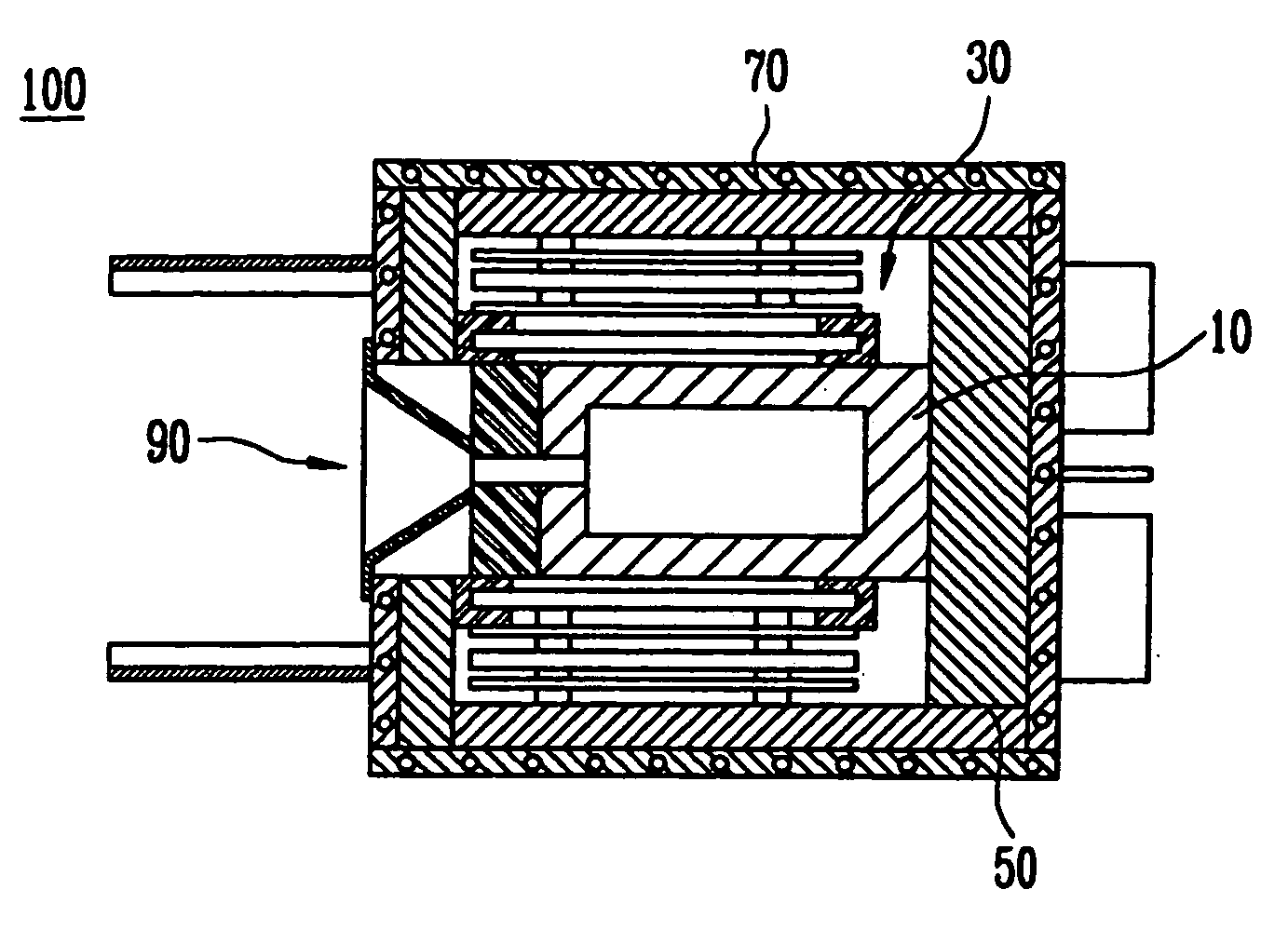
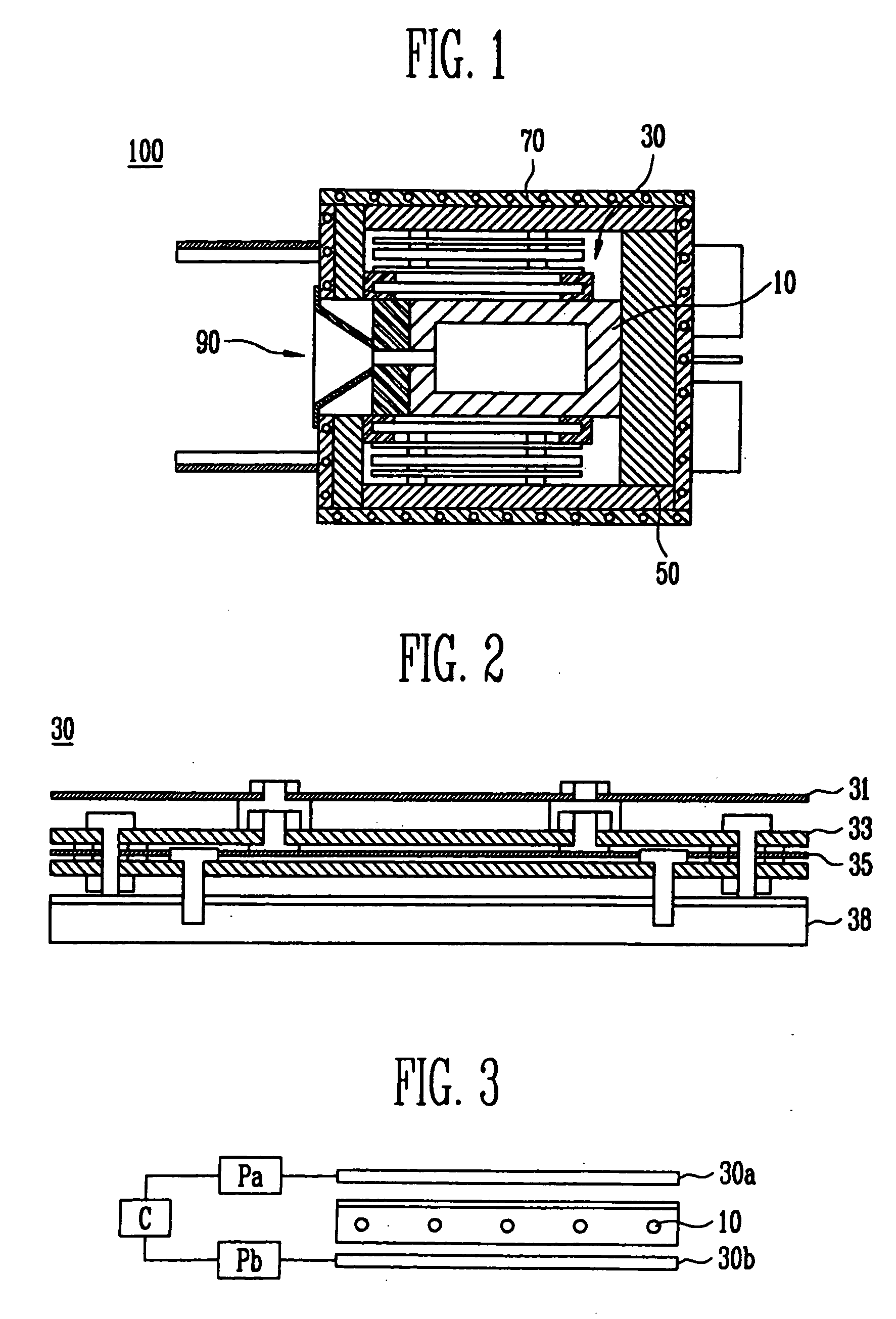
[0026]FIG. 1 illustrates an apparatus for depositing an organic layer according to one embodiment of the present invention and FIG. 2 illustrates the heating unit used in the apparatus of FIG. 1. FIG. 3 schematically illustrates the structure of the apparatus of FIG. 1.

[0027] According to one embodiment of the present invention, the apparatus for depositing an organic layer 100 includes a crucible 10 positioned in a deposition chamber (not shown), the crucible containing deposition materials. The apparatus 100 also includes a heating unit 30 which comprises first and second heat sources 30a and 30b (shown in FIG. 3) for applying heat to the crucible 10. A housing 50 is provided for isolating the heat emitted from the heating unit 30. An outer wall 70 anchors the crucible 10, and a nozzle 90 sprays the materials evaporated from the crucible 10 onto a substrate (not shown). The heating unit 30 comprises a first heat source 30a positioned near the upper portion of the crucible 10, and...


PUM

PropertyMeasurementUnit
temperatureaaaaaaaaaa
temperaturesaaaaaaaaaa
poweraaaaaaaaaa

Abstract

An apparatus for depositing an organic layer and a method for controlling the heating unit thereof are provided. The apparatus includes a crucible positioned in a deposition chamber and containing materials for evaporation. The apparatus also includes a heating unit having first and second heat sources for heating the crucible. A housing isolates the heat emitted from the heating unit and an outer wall anchors the crucible. A nozzle sprays the materials evaporated from the crucible. The first and second heat sources are positioned on first and second sides of the crucible, respectively, and are independently controlled to minimize the time required to stabilize the deposition rate.

Description

CROSS-REFERENCE TO RELATED APPLICATIONS [0001] This application claims priority to and the benefit of Korean Patent Application No. 2005-80997, filed on Aug. 31, 2005, in the Korean Intellectual Property Office, the entire content of which is incorporated herein by reference. FIELD OF THE INVENTION [0002] The present invention relates to an apparatus for depositing an organic layer and to a method for controlling a heating source thereof. More specifically, the invention is directed to an apparatus for depositing an organic layer capable of improving deposition efficiency, preventing condensation of the nozzle, and controlling temperature by minimizing the time required to stabilize the deposition rate. BACKGROUND OF THE INVENTION [0003] Generally, a deposition apparatus is used to deposit thin films on various electronic parts. In particular, the deposition apparatus is used to form thin films on electronic devices and display devices such as semiconductors, LCDs, organic electrolu...

Claims


Application Information

Patent Timeline
Patent Type & Authority Applications(United States)
IPC IPC(8): C23C16/00
CPCC23C14/243C23C14/12C23C14/24C23C14/26C23C14/541C23C14/542
Inventor JEONG, MIN JAEKIM, DO GEUNJEONG, SEOK HEON
Owner SAMSUNG DISPLAY CO LTD
Why Eureka
Try Eureka