Brazing techniques for dense high-fired alumina

Inactive Publication Date: 2007-04-05
BATTELLE MEMORIAL INST
View PDF13 Cites 4 Cited by
  • Summary
  • Abstract
  • Description
  • Claims
  • Application Information

AI Technical Summary

Benefits of technology

[0007] It is therefore an object of the present invention to form a durable bond between two dense ceramic parts. It is a further object of the present invention to form a durable bond between two ceramic parts that will maintain structural integrity in high tempe

Problems solved by technology

Unfortunately, to date many of the known methods for joining one ceramic part to another ceramic part fail to form a durable bond that can withstand the sometimes harsh environments where the combination may be used.
Typically, the bond where two parts are joined is the weakest point where this

Method used


Image

  • Brazing techniques for dense high-fired alumina
  • Brazing techniques for dense high-fired alumina
  • Brazing techniques for dense high-fired alumina

Examples


example 1

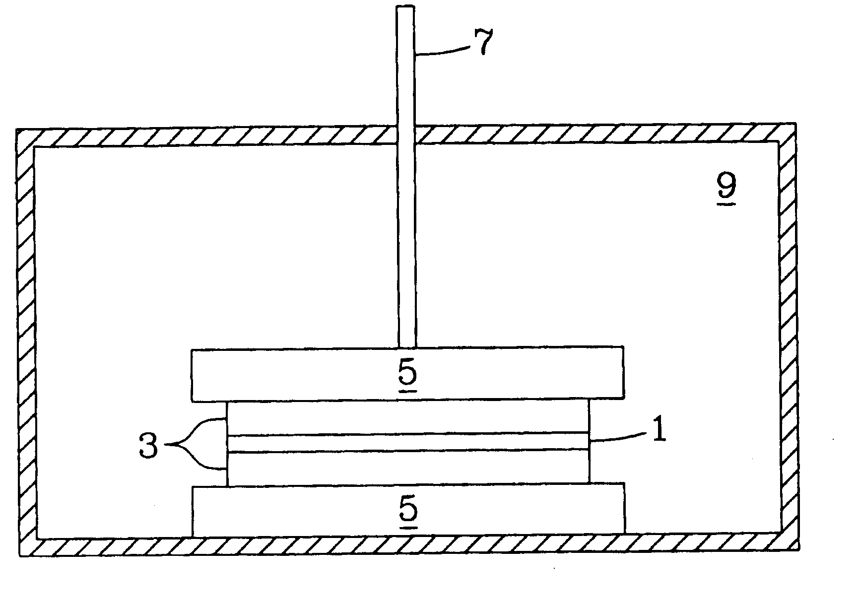
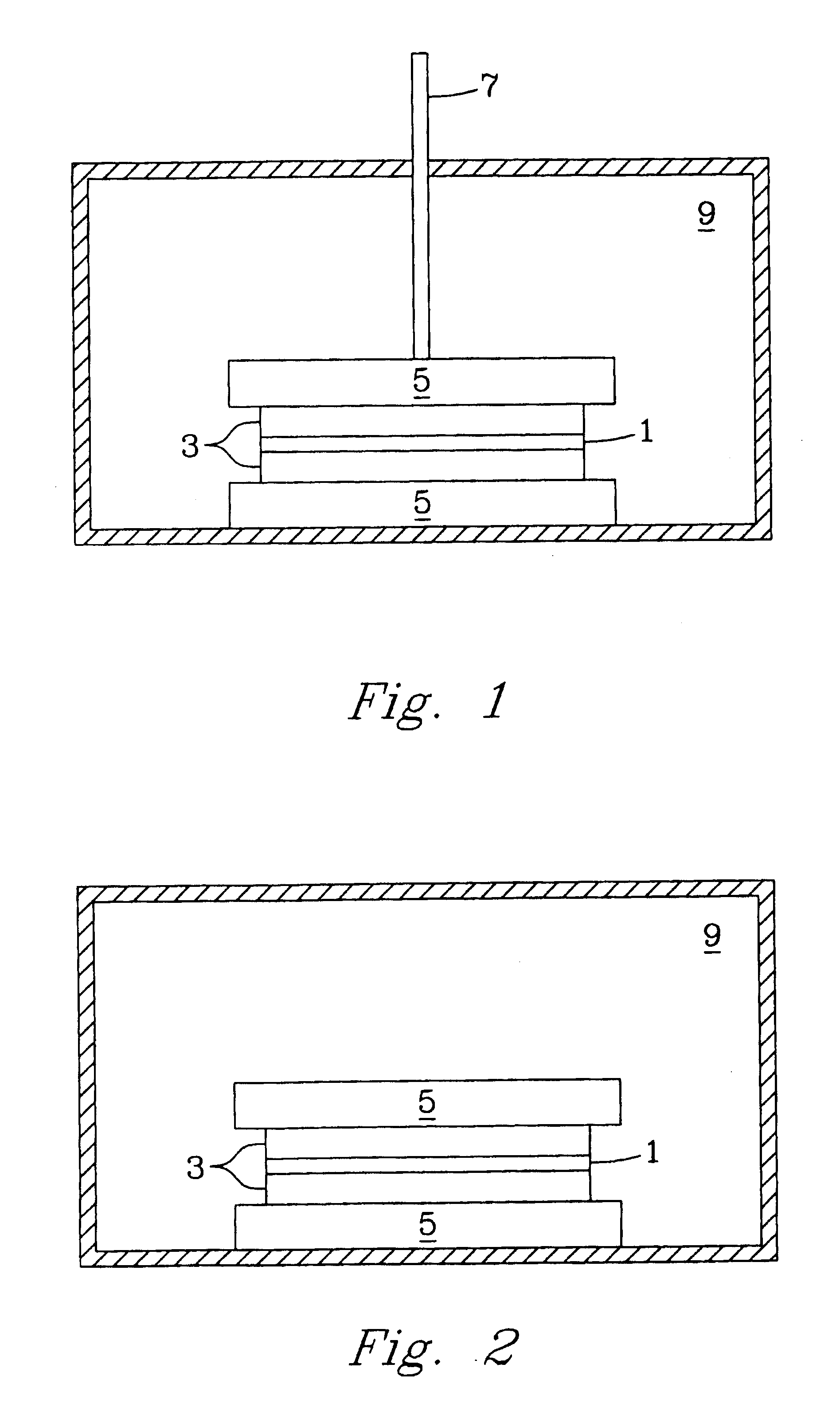
[0034] The pressure-assisted method included the application of pressure on testing samples during heat treatment after a layer of LiAl5O8 fine powder or paste was applied to the joint area. The LiAl5O8 paste was formed by mixing the fine powder of LiAl5O8 and a binder system, for example, Ferro B71757. LiAl5O8 powder is insoluble in water and does not react with the organic based binder system. After the applied paste was pre-dried in air for about 4 hours, the specimen was pressed using an alumina rod with a pressure of about 5 to about 40 psi. The sample was heated at 1° C. / min to 400° C. and held for 1 hour to burn out the binder, then heated at 3° C. / min to 1450° C.-1500° C. and held for 2 hours. The bonding strength is higher than 6000 psi as determined by the shear strength method test described herein.

example 2

[0035] In another example of the pressure-less method involved applying a thin layer of Li5AlO4 fine powder or paste evenly over the entire braze area of two dense alumina bars (1″×¼″×⅛″ each) and heating the substrates at 10° C. / min to 1200° C. and holding at the temperature for a period in the range of about 2-12 hours. At the 1200° C. temperature plateau, the Li5AlO4 powder melts and wets the surface of the fired alumina bars and starts to react to form other lithium aluminate compounds with higher Al / Li ratio to the precursor Li5AlO4 powder. The bonding strength of the sample was about 725 psi using a shear strength measurement. The brazed interface consists of mainly LiAlO2 phase with less than 20% of LiAl5O8 phase identified by X-ray diffraction (XRD) analysis.

example 3

[0036] In a further example of the pressure-less method also involved placing a thin layer of Li5AlO4 fine powder or paste in the braze area of two dense alumina parts and heating the substrates at 10° C. / min to 1400° C. and holding at that temperature for 12 hours. The high temperature refractory LiAl5O8 was dominantly formed at the brazed interface. The bonding strength of the test sample was less than 725 psi using a shear strength method test.


PUM

PropertyMeasurementUnit
Temperatureaaaaaaaaaa
Pressureaaaaaaaaaa
Refractoryaaaaaaaaaa

Abstract

The present invention discloses a refractory bond and method of making the same. The refractory bond is achieved by forming such bond between two dense ceramic parts using a lithium containing material which is reacted with at least the surface of the two dense ceramic parts. More specifically, the bond is formed of a material consisting of lithium oxide-x wherein x is the same material as the dense ceramic parts. Also preferred, but not to be limiting, the bond is in the form of lithium, and the bond together with the dense ceramic parts are in a solid solution. The invention is broadly applicable to all ceramic parts; however, preferred ceramic parts are selected form the group consisting of alumina, zirconia, titania, and magnesia.

Description

[0001] The invention was made with Government support under Contract DE-AC0576RLO 1830, awarded by the U.S. Department of Energy. The Government has certain rights in the invention.TECHNICAL FIELD [0002] This invention relates to refractory bond and method of making the same for bonding ceramic parts. More specifically, this invention relates to forming a refractory bond between two dense ceramic parts using a lithium containing material reacted with at least the surface of the two dense ceramic parts. BACKGROUND OF THE INVENTION [0003] There are a great many uses for ceramic instruments in a wide variety of industrial applications. Common to many of these applications is the need to bond different ceramic parts together to form the desired product. Unfortunately, to date many of the known methods for joining one ceramic part to another ceramic part fail to form a durable bond that can withstand the sometimes harsh environments where the combination may be used. [0004] For example, ...

Claims


Application Information

Patent Timeline
IPC IPC(8): C03B29/00B23K31/02B32B19/00
CPCB23K20/023B23K20/233B23K2203/16C04B37/005C04B2237/064C04B2237/068C04B2237/34C04B2237/343C04B2237/346C04B2237/348C04B2237/562C04B2237/60B23K2103/16
Inventor HOLLENBERG, GLENN W.BAGAASEN, LARRY A.XIA, GUANGUANG
Owner BATTELLE MEMORIAL INST
Why Eureka
Try Eureka