Drainage apparatus and method

a technology of draining apparatus and draining tube, which is applied in the direction of prosthesis, wound draining, infusion syringe, etc., can solve the problems of clogging the catheter or the drainage tube, fluids cannot be readily absorbed into the fluid collection container, and the tube has to be removed, so as to achieve the effect of simple and convenient removal

Inactive Publication Date: 2007-04-05
MEDELA HLDG AG
View PDF7 Cites 98 Cited by
  • Summary
  • Abstract
  • Description
  • Claims
  • Application Information

AI Technical Summary

Benefits of technology

[0007] It is an object of the invention to provide a method and an apparatus for removing fluids from a body cavity which enables removal of clots in the catheter and the drainage tube in a more simple and more expedient way.
[0009] The inventive apparatus for removing body fluids from a body cavity by suction, such as a thorax, gastric or any other human body cavity or from a wound, comprises the same basic elements as the apparatus known in the prior art. However, means are provided to increase the pressure difference between a pressure in a drainage lumen and a pressure in the atmosphere when an auxiliary lumen is open. In a preferred embodiment, this means is a control which controls a suction pump and which therefore increases the suction power of the suction pump.
[0011] However, by increasing the pressure in the drainage lumen at the distal end of the drainage lumen, the clot in the drainage lumen or the catheter can be removed through this distal end without any risk that any damages in the cavity may occur.
[0013] Clots can therefore easily be removed, without having to disturb the patient by removing and reentering the drainage tube.

Problems solved by technology

The negative pressure applied has to be chosen carefully, since excessive pressure may damage delicate tissues in the body cavity.
Blood or tissue clots however can clog the catheter or the drainage tube, such that the fluids can no longer readily drain into the fluid collection container but tend to built up in the catheter, the drain tube or may even remain in the cavity.
However, the catheter and the drainage tube have still to be removed and cleaned, when they are clogged.

Method used


Image

  • Drainage apparatus and method
  • Drainage apparatus and method
  • Drainage apparatus and method

Examples


Embodiment Construction

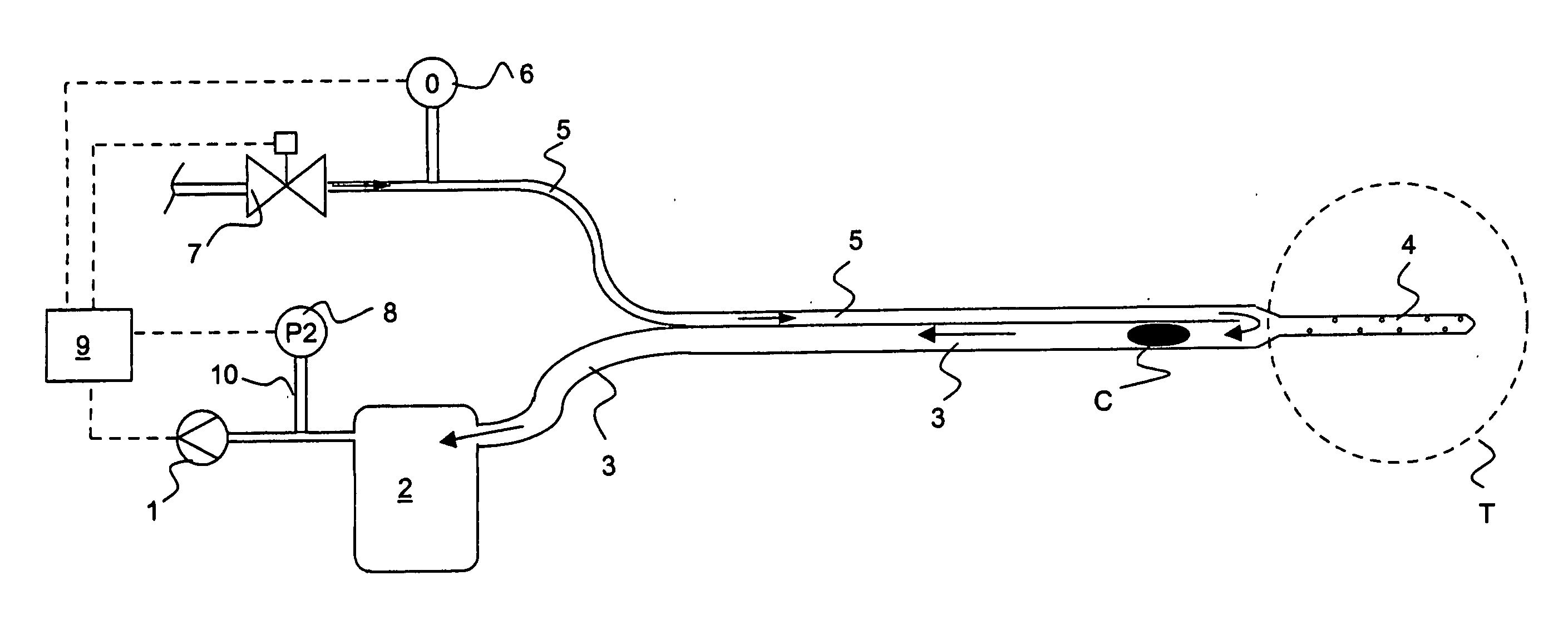
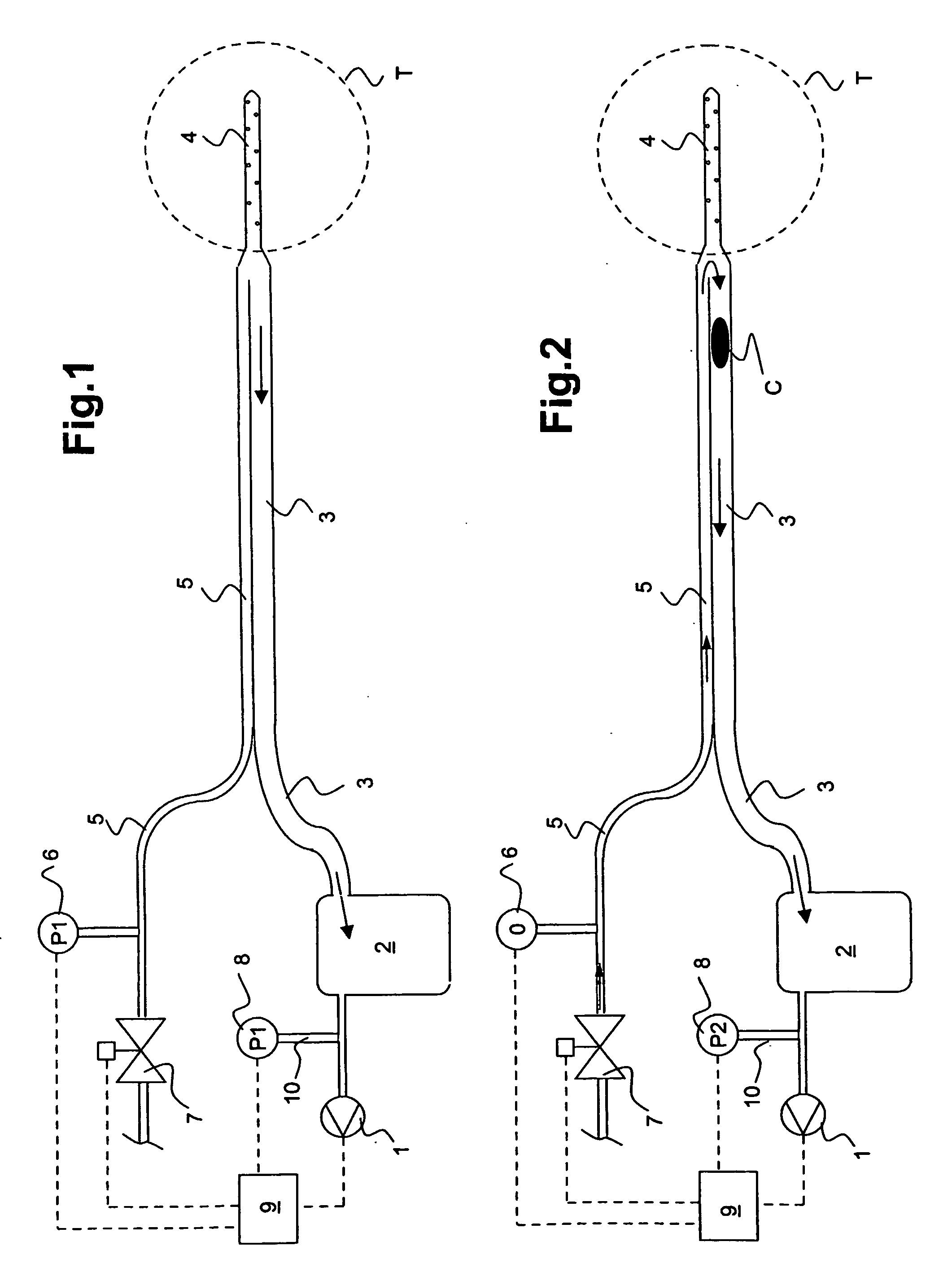
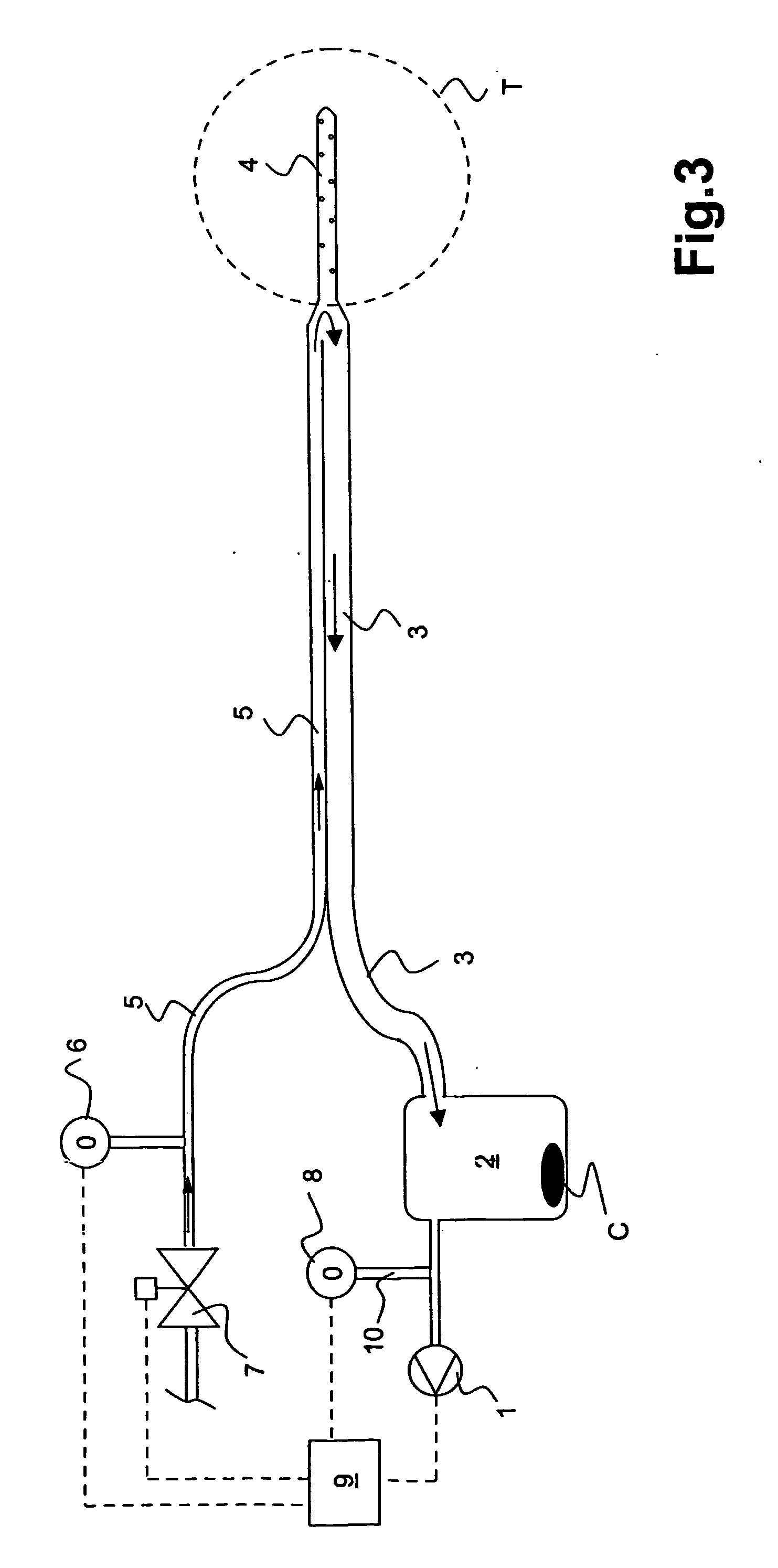
[0019] The apparatus according to the invention comprises a suction source, preferably a suction pump 1; suction drainage collection means comprising a drainage fluid collection container 2 or comprising a container system having in addition an underwater seal container; a catheter means comprising a drainage lumen 3, a catheter 4 and an auxiliary lumen 5; a first pressure sensor 6; a valve 7; a second pressure sensor 8 and a controller 9.

[0020] The suction pump 1 is connected to the drainage fluid collection container 2 by a tube 10. The second pressure sensor 8 measures the pressure in this tube 10. The second pressure sensor 8 can also be placed in the fluid collection container 2 or the drainage lumen 3. The drainage fluid collection container 2 is closed by an airtight lid. So is the underwater seal, when one is used. The drainage lumen 3 comprises a distal end, which is connected to an opening of the container 2. The proximal end of the drainage lumen 3 ends in the catheter 4...


PUM


Abstract

An apparatus for removing body fluids from a body cavity by suction, such as a thorax, gastric or any other human body cavity or a wound, comprises means (9) to increase the pressure difference between a pressure in a drainage lumen (3) and a pressure in the atmosphere when an auxiliary lumen (5) is open. The apparatus enables removal of clots or other plugs of the catheter and drainage tube in an efficient and not patient disturbing way.

Description

TECHNICAL FIELD [0001] This invention relates to a drainage apparatus and a method for removing fluids from a body cavity, preferably a chest drainage apparatus. BACKGROUND OF THE INVENTION [0002] A drainage apparatus is used for draining fluid from a human body cavity or wound to promote healing, such as after chest surgery. The apparatus usually comprises a suction pump, a collection container which is often connected with an underwater seal container, and a drainage tube having a distal and a proximal end. The proximal end of this tube is connected to a catheter which is introduced in the body cavity, the distal end extends into the collection container or the underwater seal container respectively. The negative pressure applied has to be chosen carefully, since excessive pressure may damage delicate tissues in the body cavity. [0003] Blood or tissue clots however can clog the catheter or the drainage tube, such that the fluids can no longer readily drain into the fluid collectio...

Claims


Application Information

Patent Timeline
Patent Type & Authority Applications(United States)
IPC IPC(8): A61M1/00
CPCA61M1/0031A61M1/0084A61M2205/3569A61M2210/101A61M1/0035A61M1/743A61M1/74A61M1/85A61M1/90
Inventor LARSSON, MICHAEL
Owner MEDELA HLDG AG
Why Eureka
Try Eureka