Upright vacuum cleaner

Inactive Publication Date: 2007-04-12
LG ELECTRONICS INC
View PDF11 Cites 24 Cited by
  • Summary
  • Abstract
  • Description
  • Claims
  • Application Information

AI Technical Summary

Benefits of technology

[0013] An object of the present invention is to provide a vacuum cleaner which has a simple coupling structure, and is convenient in use.
[0014] Another object of the present invention

Problems solved by technology

Such cyclonic airflow upright vacuum cleaners have not been found to be entirely effective and convenient to use.
For example, with these cyclonic airflow vacuum cleaners, the coupling structure of the dust collector is complex, thereby causing an inconvenience in use of the vacuum cleaner.
Also, in the vacuum cleaner having the above-mentioned configuration, t

Method used


Image

  • Upright vacuum cleaner
  • Upright vacuum cleaner
  • Upright vacuum cleaner

Examples


Embodiment Construction

[0049] Reference will now be made in detail to the preferred embodiments of the present invention, examples of which are illustrated in the accompanying drawings.

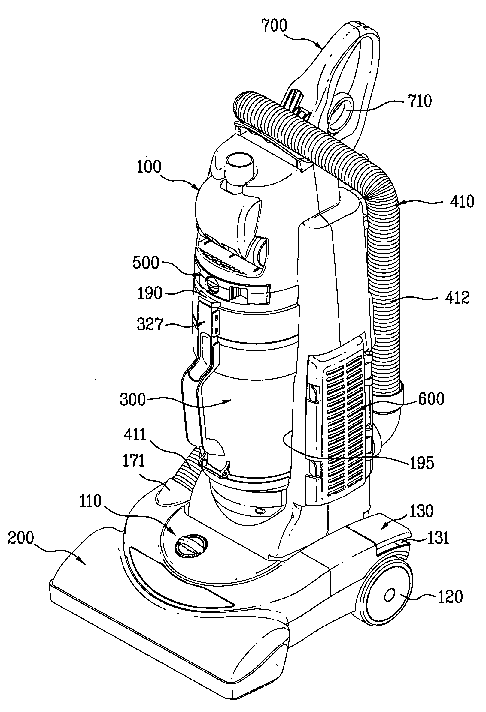
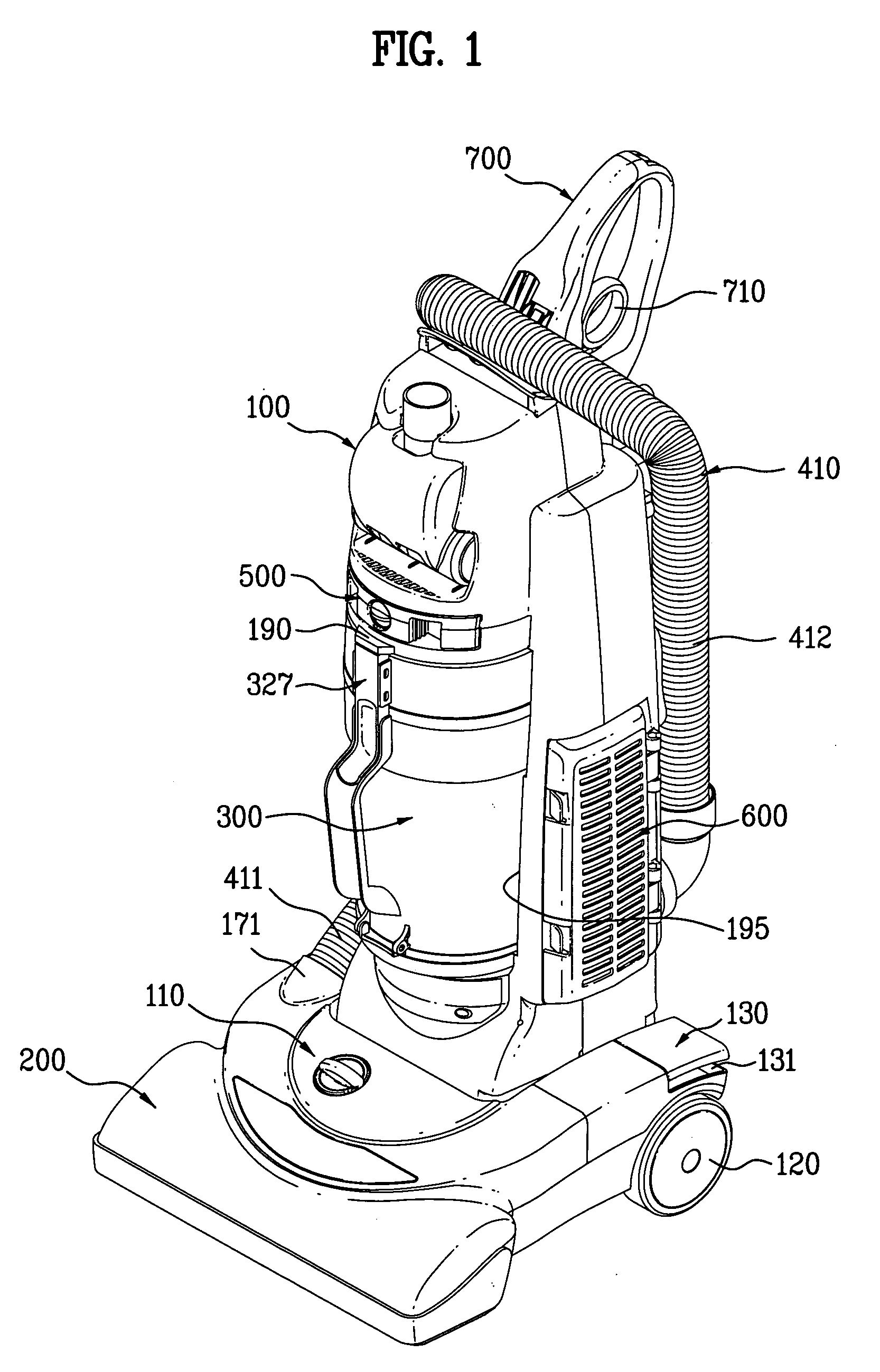
[0050]FIGS. 1-6 illustrate an upright vacuum cleaner including a cleaner body 100, a nozzle section 200 connected to the cleaner body 100, and conduits for guiding the suction airflow from the nozzle section 200 to the atmosphere with passing through the cleaner body 100.

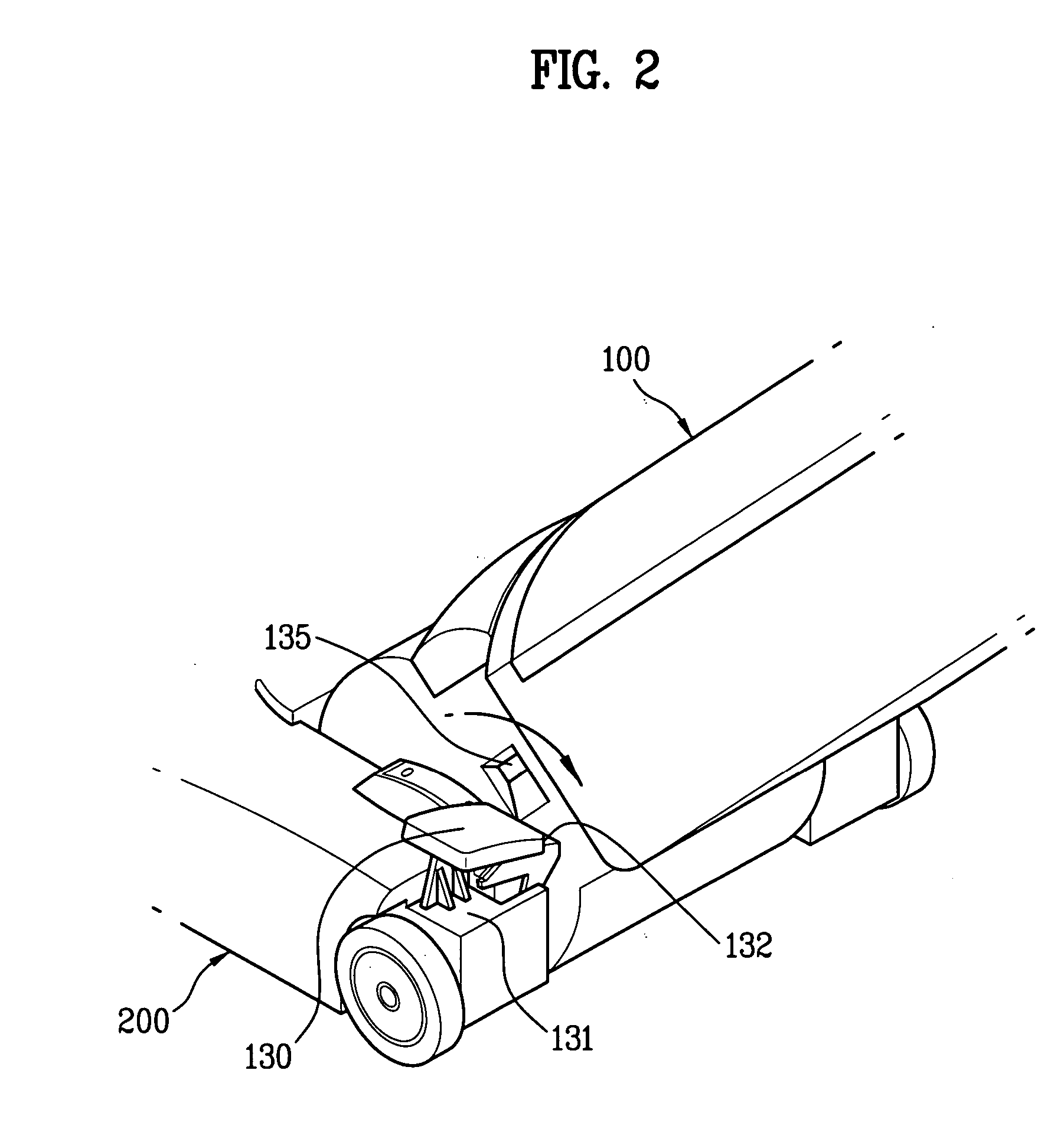
[0051] The cleaner body 100 and the nozzle section 200 are pivotally or hingedly connected through the use of suitable hinge assembly so that the cleaner body 100 pivots between a generally vertical storage position (as shown) and an inclined operative position.

[0052] The hinge assembly includes a rotation shaft 150 and rotating shaft holes 151 corresponding to the rotation shaft 150. The rotation shaft 150 protrudes from two lower opposing sides of the cleaner body 100 and the rotating shaft holes are provided at nozzle section 200 for retaining the rot...


PUM


Abstract

A vacuum cleaner is disclosed. The vacuum cleaner comprises a cleaner body, a cyclonic chamber comprising a primary cyclone and at least one secondary cyclone disposed around the primary cyclone, a flow passage guide for guiding the airflow discharged from the primary cyclone to a secondary airflow inlet of the secondary cyclone, a first conduit for fludically connecting a nozzle section defining a suction opening to a primary airflow inlet of the primary cyclone, a suction source having an suction source inlet and an suction source outlet, and a second conduit for fludically connecting a secondary airflow outlet to the suction source inlet of the suction source. Accordingly, it is possible to achieve a low flow resistance by virtue of the flow passage guide and an enhanced dust collecting performance by virtue of a sealing effect of the sealing member.

Description

BACKGROUND OF THE INVENTION [0001] 1. Field of the Invention [0002] The present invention relates to vacuum cleaners. More particularly, the present invention relates to upright vacuum cleaners used for suctioning dirt and dust from carpets and floors. [0003] 2. Discussion of the Related Art [0004] Upright vacuum cleaners are known to include a cleaner body having a handle, by which an operator of the vacuum cleaner may grasp and maneuver the cleaner, and a nozzle section which travels across a floor, carpet, or other surfaces being cleaned. [0005] The cleaner body often formed as a rigid plastic housing which encloses a dirt and dust collecting filter bag. The underside of the nozzle section includes a suction opening formed therein which is in fluid communication with the filter bag. [0006] A suction source such as a motor and fan assembly is enclosed within the cleaner body. The suction source generates the suction force required to pull dirt from the carpet or floor through the ...

Claims


Application Information

Patent Timeline
IPC IPC(8): A47L9/16
CPCA47L5/30A47L9/122A47L9/1625A47L9/1641A47L9/165A47L9/1683
Inventor MIN, YOUNGKIM, JAE
Owner LG ELECTRONICS INC
Why Eureka
Try Eureka