Solar rail or railing system

a solar panel and solar panel technology, applied in the direction of light radiation electric generators, generators/motors, lighting and heating equipment, etc., can solve the problems of difficult and dangerous access to locations, the area of roofs that may receive solar panels relative to the volume of buildings that need electric supply is too limited, and the cost of transmission creates a second problem

Inactive Publication Date: 2007-04-12
MORALI ANTHONY
View PDF5 Cites 58 Cited by
  • Summary
  • Abstract
  • Description
  • Claims
  • Application Information

AI Technical Summary

Benefits of technology

[0007] Therefore, the invention combines the interest in photovoltaic technology, with available space at a location of energy use as a rail or railing system for a building. In particular, the rail or railing system may be used about high-rise balconies. The rail or railing system has one or more solar panels above, below or between a bottom, top or bottom and top rails that provide support to each panel and connection between panels.

Problems solved by technology

Two problems with this have been encountered.
One is that present solar cells produce only small amounts of electricity, so that large areas need to be covered with solar cells to generate meaningful supplies of electricity.
Is these large areas are located in remote areas where the space is cheap, then transmission costs create a second problem in conducting the electricity to a location for use.
Such locations are difficult and dangerous to access.
Moreover, when the roof is that of a high-rise building, the area of roof that may receive solar cells relative to the volume of building that needs electric supply is too limited, even when the building roof is designed to receive the solar cells like the CitiCorp building in New York City.

Method used


Image

  • Solar rail or railing system
  • Solar rail or railing system
  • Solar rail or railing system

Examples


Embodiment Construction

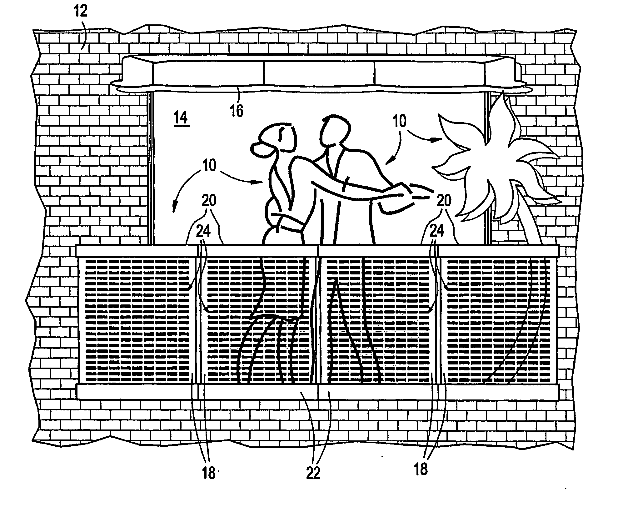
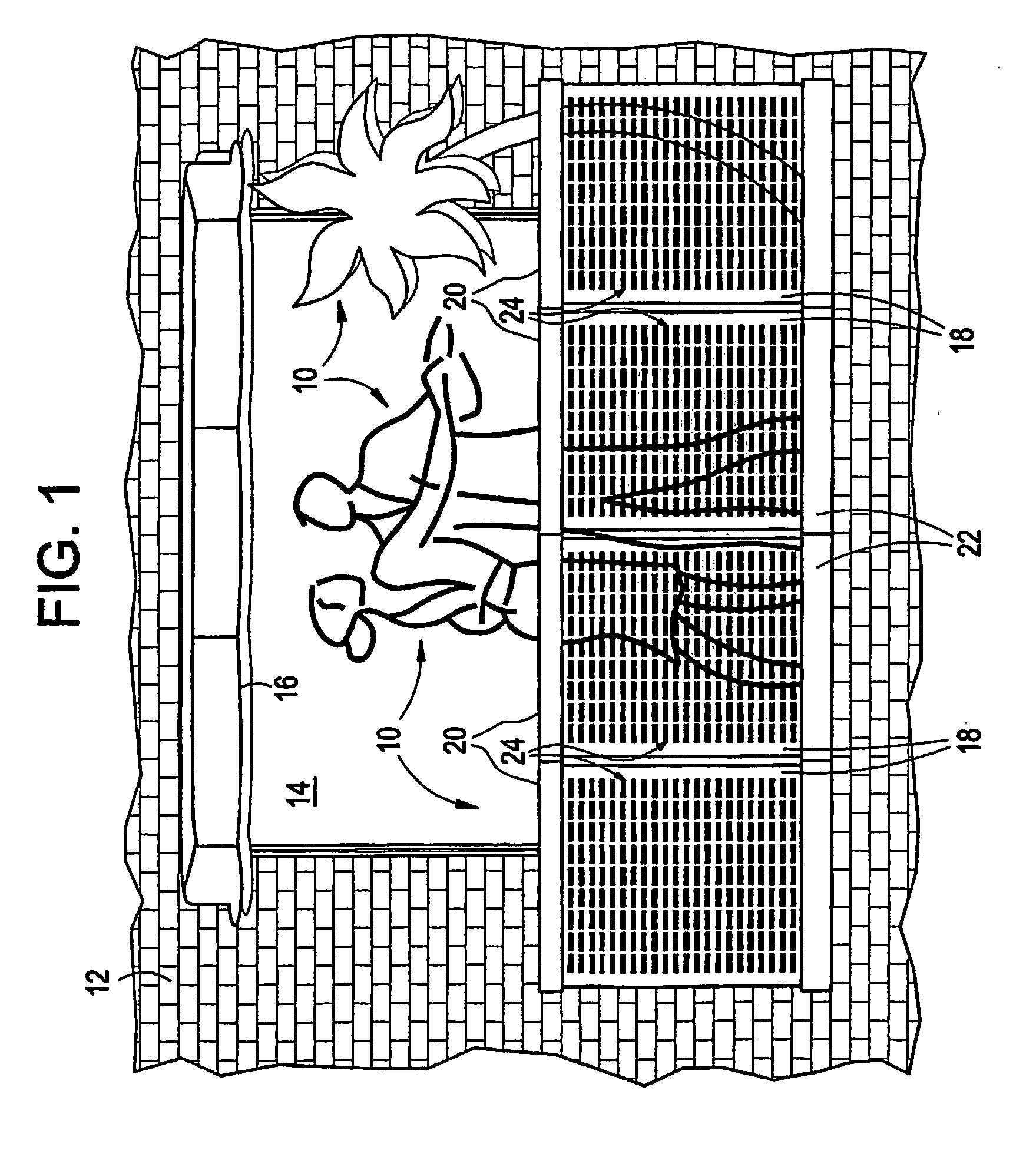
[0019] In FIG. 1, people and plants at 10 stand on a projecting balcony (not shown) of a building portion 12. An entry 14 from the balcony into the building may be shaded by an awning 16 but, as general in such cases, the awning would not project far enough from the building to shade as well panel sections 18 about a perimeter of the balcony as part of a solar rail or railing system.

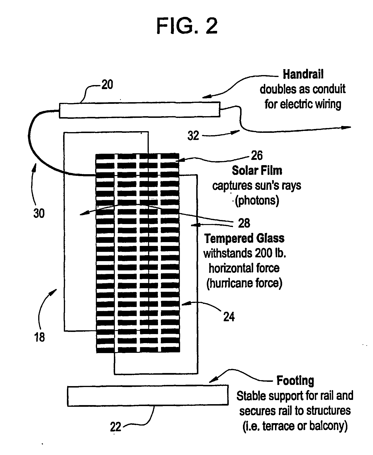
[0020] The panel sections have respective top rail sections 20 and bottom rail sections 22. The top rail sections interconnect to form a top rail element or handrail and the bottom rail sections interconnect to form a bottom rail element all along the panel sections for structural strength. The bottom rail element or footing provides a stable support for the panel sections and secures the panel sections to a building structure such as the balcony or terrace, which is behind it in this embodiment and, therefore, not shown.

[0021] The panel sections have respective arrays of discrete, opaque solar cells a...


PUM


Abstract

A panel for a solar rail or railing system has first and second transparent or, at least, translucent tempered glass panels, an array of solar cells (24) spaced from but connected to each other on a transparent or, at least, translucent film sandwiched between the glass panels, a bottom rail (22) for supporting the sandwich of film and glass panels from a portion of a building, and a top rail (20) for an outlet conduit of the electrical connection of the solar cells.

Description

BACKGROUND OF THE INVENTION [0001] The invention relates to locating photovoltaic units such as solar cells in a rail or railing system, for example as balustrade panels above, below or between connecting rails extending, for example, horizontally about high-rise balconies. [0002] Resource conservation, environmental concerns and other energy costs have promoted interest in photovoltaic technology that converts light and, preferably, sunlight into electricity. Two problems with this have been encountered. One is that present solar cells produce only small amounts of electricity, so that large areas need to be covered with solar cells to generate meaningful supplies of electricity. Is these large areas are located in remote areas where the space is cheap, then transmission costs create a second problem in conducting the electricity to a location for use. [0003] Therefore, it has been considered to put solar cells on the otherwise unused space of building roofs. Such locations are dif...

Claims


Application Information

Patent Timeline
Patent Type & Authority Applications(United States)
IPC IPC(8): H02N6/00H01L31/042H01L31/048H01L31/05
CPCE04F11/1851F24J2/0427H01L31/02008H02S20/00Y02B10/10Y02B10/20Y02E10/50H01L31/048H02S20/26H01L31/0488F24S20/62
Inventor MORALI, ANTHONY
Owner MORALI ANTHONY
Why Eureka
Try Eureka