Heat cooking apparatus, cooking tool and heat cooking system
- Summary
- Abstract
- Description
- Claims
- Application Information
AI Technical Summary
Benefits of technology
Problems solved by technology
Method used
Image
Examples
embodiment 1
[0034] A first embodiment of implementation of the invention will be described in connection with FIGS. 1 and 10.
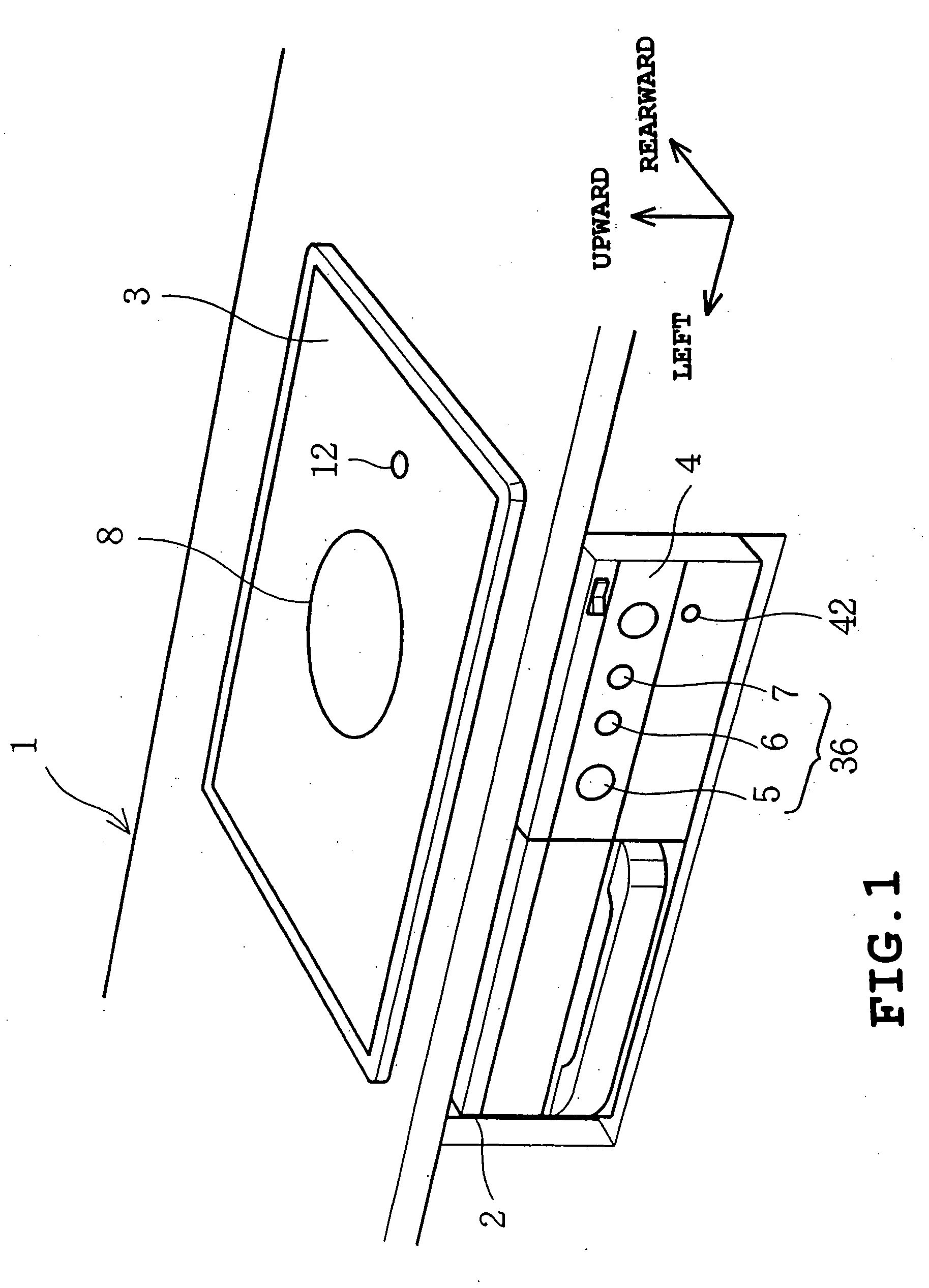
[0035]FIG. 1 is a perspective view illustrating the external appearance of a cooking heater. In the interior of a system kitchen 1 is received a cabinet 2. On the upper surface of the cabinet 2 is provided a top plate 3 made of heat-resistant glass corresponding to supporting unit. The top plate 3 is exposed at the upper surface of the system kitchen 1. The top plate 3 is colored to opacity so that the interior of the cabinet 2 cannot be seen through the top plate 3.
[0036] In front of the cabinet 2 is provided a control panel 4 provided with an automatic water boiling key 5, a caloric force adjusting dial 6 and a tempura (Japanese deep-fat fried food) key 7. These keys correspond to units of inputting cooking conditions. In this arrangement, control can be made on the front.
[0037] On the top plate 3 is formed a circular heating mark 8. The heating mark 8 is colored to ...
embodiment 2
[0101] A second embodiment of implementation of the invention will be described in connection with FIGS. 11 and 13.
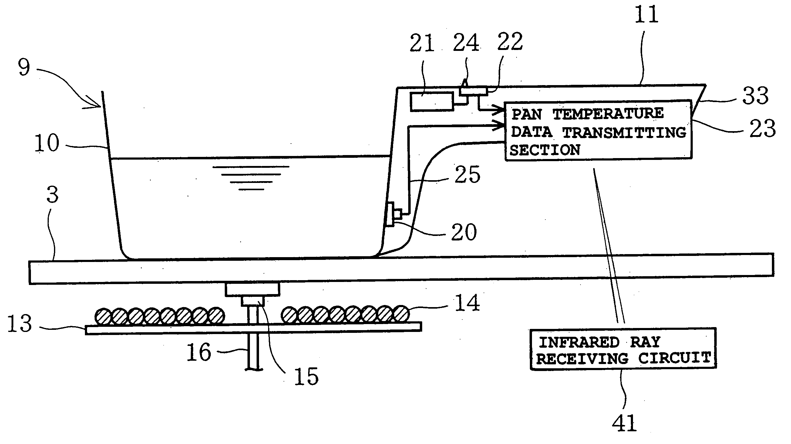
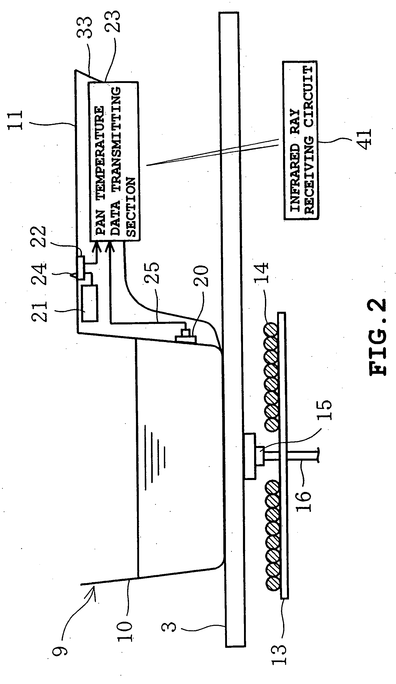
[0102]FIG. 11 depicts a dedicated cooking tool 9 set on a top plate 3. FIG. 12 depicts the electrical configuration of a temperature data transmitting portion 23 and its peripheral circuits.
[0103] The handgrip 11 of the dedicated cooking tool 9 has a temperature switch 43 provided in a handgrip cover 33 as a switching unit. The pan electric supply 21 is connected to an electric supply circuit 26 via the temperature switch 43. The temperature switch 43 has a bimetal as a moving contact. The temperature switch 43 switches ON or OFF across the detected temperature Tb as a border. In some detail, when the surface temperature To of the cooking tool 9 is not greater than the detected temperature Tb, the temperature switch 43 switches OFF to deenergize the temperature data transmitting portion 23. On the contrary, when the surface temperature To of the cooking tool 9 exceeds...
embodiment 3
[0106] A third embodiment of implementation of the invention will be described in connection with FIGS. 14 to 16.
[0107]FIG. 14 depicts a dedicated cooking tool 9 set on a top plate 3. FIG. 15 depicts the electrical configuration of the temperature data transmitting portion 23 and its peripheral circuits.
[0108] The dedicated cooking tool 9 has an annular loop coil 44 attached thereto on the lower surface of the container portion 10. The loop coil 44 is a secondary coil which is magnetically connected to IH coil 14 while the cooking tool 9 is set on the heating mark 8 of the top plate 3. The loop coil 44 is connected to the rectifying circuit 45 of the temperature data transmitting portion 23. The rectifying circuit 45 is adapted to rectify the induced voltage of the loop coil 44. The rectifying circuit 45 has a switching electric supply circuit 46 corresponding to stabilizing electric supply portion connected thereto. The switching electric supply circuit 46 is adapted to keep the ...
PUM
 Abstract
Description
Claims
Application Information
 - R&D
- Intellectual Property
- Life Sciences
- Materials
- Tech Scout
- Unparalleled Data Quality
- Higher Quality Content
- 60% Fewer Hallucinations
Browse by: Latest US Patents, China's latest patents, Technical Efficacy Thesaurus, Application Domain, Technology Topic, Popular Technical Reports.
© 2025 PatSnap. All rights reserved.Legal|Privacy policy|Modern Slavery Act Transparency Statement|Sitemap|About US| Contact US: help@patsnap.com


