Digital clock frequency multiplier

a digital clock and multiplier technology, applied in oscillator generators, generating/distributing signals, pulse techniques, etc., can solve the problems of increased costs, inability to quickly change the frequency of input clock signals, and only suited plls

Active Publication Date: 2007-04-12
NXP USA INC
View PDF9 Cites 16 Cited by
  • Summary
  • Abstract
  • Description
  • Claims
  • Application Information

AI Technical Summary

Problems solved by technology

However, PLLs require much time and design effort to ensure stability, consume large silicon area and often require external components for usage, resulting in increased costs.
Additionally, because PLLs have high lock times, t

Method used


Image

  • Digital clock frequency multiplier
  • Digital clock frequency multiplier
  • Digital clock frequency multiplier

Examples


Embodiment Construction

[0009] The detailed description set forth below in connection with the appended drawings is intended as a description of the presently preferred embodiments of the invention, and is not intended to represent the only form in which the present invention may be practiced. It is to be understood that the same or equivalent functions may be accomplished by different embodiments that are intended to be encompassed within the spirit and scope of the invention.

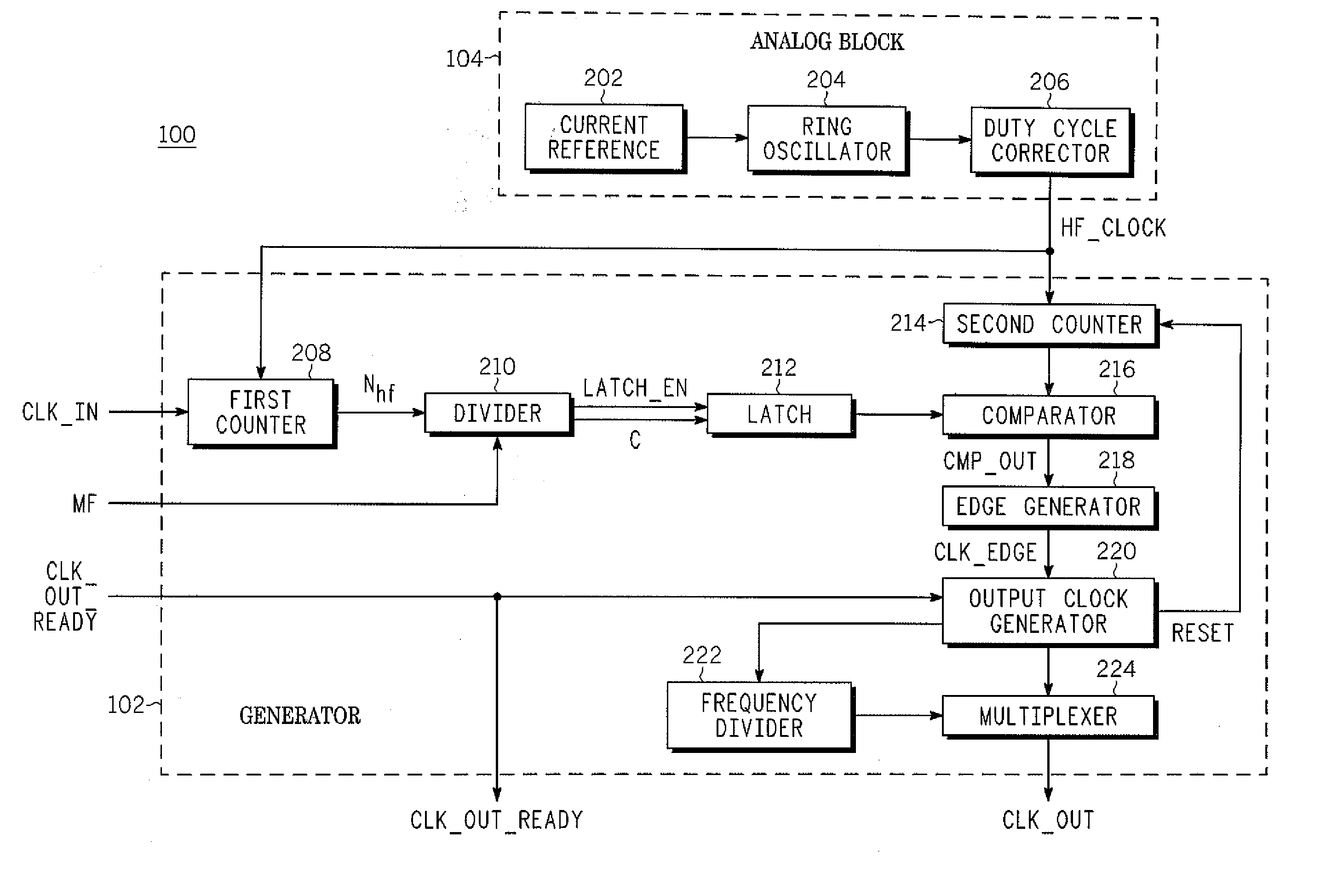
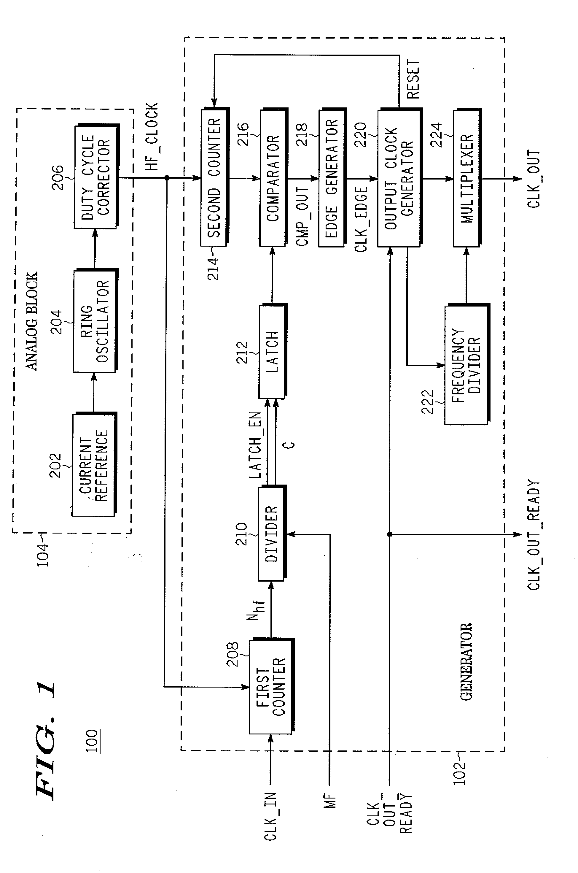
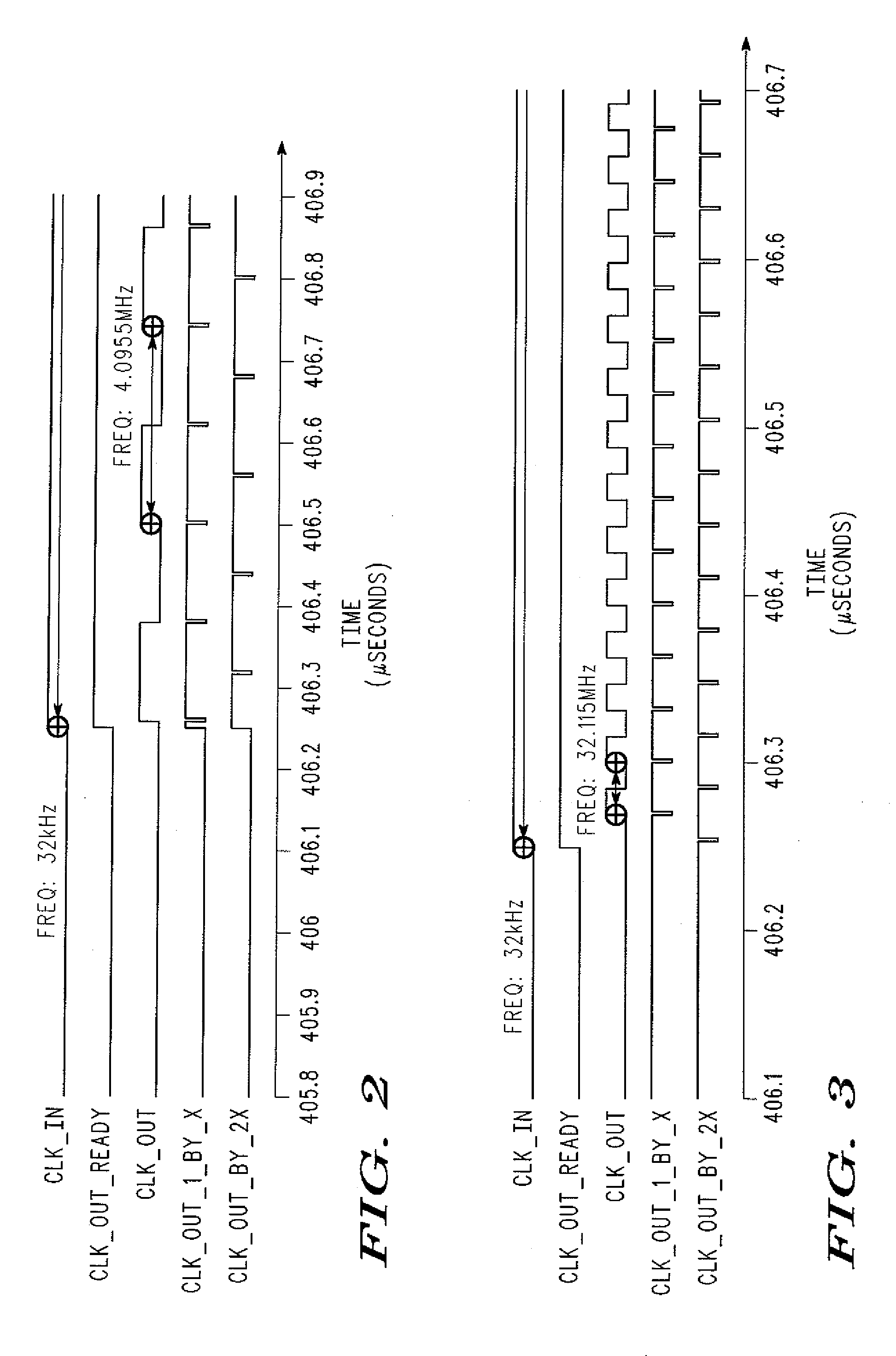
[0010] The present invention is a digital clock frequency multiplier for increasing an input frequency of an input clock signal. The digital clock frequency multiplier includes a generator that receives the input clock signal and a high frequency digital signal. The generator divides a count (Nhf) of a number of cycles of the high frequency digital signal in one period of the input clock signal by a predetermined multiplication factor (MF) for generating an output clock signal. The output clock signal has a predetermined output freq...


PUM


Abstract

A digital clock frequency multiplier (100) for increasing an input frequency of an input clock signal includes a generator (102) that receives the input clock signal and a high frequency digital signal. The generator (102) divides a count (Nhf) of a number of cycles of the high frequency digital signal in one period of the input clock signal by a predetermined multiplication factor (MF) for generating an output clock signal. The output clock signal has a predetermined output frequency.

Description

BACKGROUND OF THE INVENTION [0001] The present invention relates generally to a frequency generator for generating a digital signal and, in particular, to a digital clock frequency multiplier that increases the frequency of an input clock signal. [0002] Clock frequency multipliers are widely used in integrated circuits. Conventionally, phase locked loops (PLLs) are used as clock frequency multipliers to increase the frequency of an input clock signal. However, PLLs require much time and design effort to ensure stability, consume large silicon area and often require external components for usage, resulting in increased costs. Additionally, because PLLs have high lock times, the frequency of the input clock signal cannot be changed quickly. Further, PLLs are only suited for handling input clock signals of limited frequency and duty cycle ranges, and individual PLLs have limited multiplication ranges. [0003] In view of the foregoing, it would be desirable to have an inexpensive program...

Claims


Application Information

Patent Timeline
IPC IPC(8): H03B19/00
CPCG06F1/08G06F7/68
Inventor WADHWA, SANJAY K.MUHURY, DEEYATIWARI, PAWAN K.
Owner NXP USA INC
Why Eureka
Try Eureka