Fundus camera for wide field of view and small pupil

undus technology, applied in the field of electronic imaging apparatus for fundus imaging, can solve the problems of reducing the available power, difficult to obtain both a wide field of view and sufficient illumination, and significant obstacles to obtaining good quality images from these devices. , to achieve the effect of sufficient illumination

Inactive Publication Date: 2007-04-12
CARESTREAM HEALTH INC
View PDF12 Cites 23 Cited by
  • Summary
  • Abstract
  • Description
  • Claims
  • Application Information

AI Technical Summary

Benefits of technology

[0023] It is an advantage of the present invention that it provides sufficient illumination for retinal imaging without requiring pupil dilation in many c

Problems solved by technology

While these patents attest to continuous improvements in fundus camera design, there are still significant hurdles to obtaining good quality images from these devices.
One particularly troublesome problem relates to the need to provide illumination at levels sufficient for imaging and, at the same time, to eliminate stray light caused by unwanted reflection from the cornea that surrounds the pupil.
It is difficult to obtain both a wide field of view and sufficient illumination while keeping unwanted reflected light from the optical system.
There are two key problems with this method.
The first problem relates to the needed lamp power when using this strategy.
The use of second polarizer 112 further reduces the available power.
The second problem relates to the nature of light reflected from the cornea.
Since a portion of this light can be depolarized, particularly due to the large incident angle, second polarizer 112 will be less effective in blocking unwanted stray light.
This solution,

Method used


Image

  • Fundus camera for wide field of view and small pupil
  • Fundus camera for wide field of view and small pupil
  • Fundus camera for wide field of view and small pupil

Examples


rotating mask embodiment

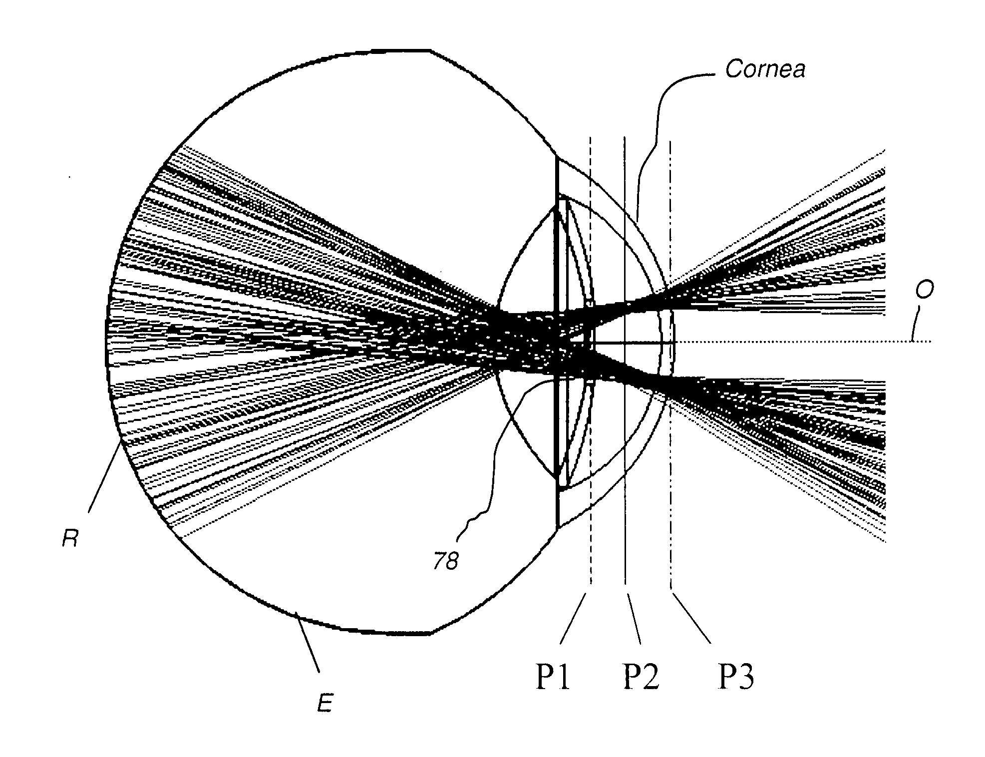
[0053] Referring to FIG. 12, there is shown an alternate embodiment using rotating masks 202 and 204. FIG. 13 shows rotating masks 202 and 204 in plan view. Mask 202 is placed at position A1, conjugate to iris plane P1. Rotating mask 204 is disposed near sensor 70. In effect, rotating mask 202 splits the pupil; rotating mask 204 splits the field. With rotating mask 202 at iris plane P1′, the cornea and pupil of the eye are partially illuminated, with the pattern of illumination shown in FIG. 14 as a partial ring 206. A full rotation of rotating mask 202 is needed in order to illuminate the whole pupil. With rotating mask 204, only a portion of the retina is imaged to sensor 70 at one time, so that a full rotation of both rotating masks 202 and 204 is necessary in order to obtain the full retinal image. Mask 204 effectively blocks light reflected from the cornea, allowing only image light to reach sensor 70. Careful alignment and angular orientation of rotating masks 202 and 204 with...


PUM


Abstract

A fundus camera (10) obtains a retinal image using a light source (62), a ring aperture (58) conjugate to the cornea, and a first aperture (54) conjugate to the iris. An apertured mirror (52) redirects the ring illumination toward the eye. An objective lens (50) between the apertured mirror (52) and the eye has an entrance pupil between the iris and the cornea of the eye. The objective lens (50) directs the ring illumination into the pupil of the eye and directs a reflected image-bearing light from the retina through the apertured mirror (52). A second aperture (64), conjugate to a plane between the cornea and the iris of the eye, forms an aperture stop for the reflected image-bearing light. A third aperture (68) is conjugate to the cornea for blocking light reflected. A sensor (70) provides an image of the retina.

Description

FIELD OF THE INVENTION [0001] This invention generally relates to electronic imaging apparatus for fundus imaging and more particularly relates to an improved fundus imaging apparatus suitable for smaller pupil diameters. BACKGROUND OF THE INVENTION [0002] Fundus camera imaging is acknowledged to be an important diagnostic tool for detection of various conditions affecting the eye, including diabetic retinopathy and macular degeneration. Various embodiments of fundus imaging apparatus are disclosed, for example in U.S. Pat. No. 5,713,047 (Kohayakawa); U.S. Pat. No. 5,943,116 (Zeimer); U.S. Pat. No. 5,572,266 (Ohtsuka); U.S. Pat. No. 4,838,680 (Nunokawa); U.S. Pat. No. 6,546,198 (Ohtsuka); U.S. Pat. No. 6,636,696 (Saito); U.S. Pat. No. 4,247,176 (Ito); U.S. Pat. No. 5,742,374 (Nanjo et al.); and U.S. Pat. No. 6,296,358 (Comsweet et al.) [0003] While these patents attest to continuous improvements in fundus camera design, there are still significant hurdles to obtaining good quality i...

Claims


Application Information

Patent Timeline
IPC IPC(8): A61B3/14
CPCA61B3/156
Inventor LIANG, RONGGUANGHAWVER, JEFFERY R.
Owner CARESTREAM HEALTH INC
Why Eureka
Try Eureka