
System and method for optimizing the topology of a virtual ring based upon a TCP/IP network

a virtual ring and topology technology, applied in the field of communication on digital networks, can solve the problems of resource consumption at the level of each node, network bandwidth consumption at the network level, and important overhead, and achieve the effect of reducing the resource consumption of inter-communicating nodes

Inactive Publication Date: 2007-04-12
IBM CORP
View PDF5 Cites 24 Cited by
  • Summary
  • Abstract
  • Description
  • Claims
  • Application Information

AI Technical Summary

Benefits of technology

The present invention is about optimizing the topology of a virtual ring used for multicast communication in a network. The invention involves a method for managing changes in the ring membership and selecting the best location for inserting a new member node. The method includes requesting other nodes to measure their communication distances to a new member node and inserting the new member node in a selected location between two selected nodes. The invention also includes sending a compute distance message to the downstream nodes and receiving distance computed messages from the upstream nodes. The technical effects of the invention include reducing communications distances and optimizing network performance.

Problems solved by technology

This is not the case with the transport protocol called UDP (User Datagram Protocol) which is based on the best effort and which does not provide any session mechanism.
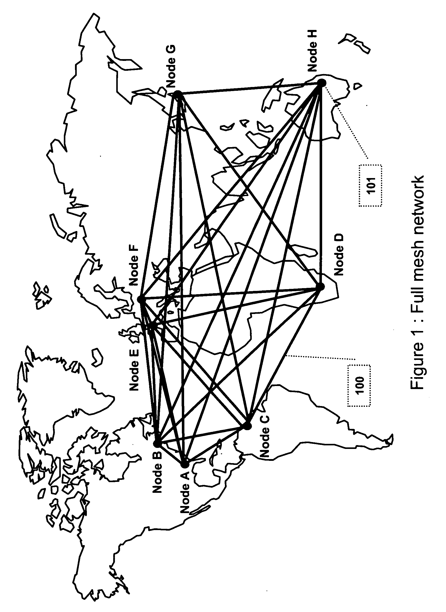
It can results in an important overhead with a significant impact in term of bandwidth consumption in the network and resource (data processing and memory) utilisation in each node.
This is bandwidth consuming at the network level and resource consuming at the level of each node.
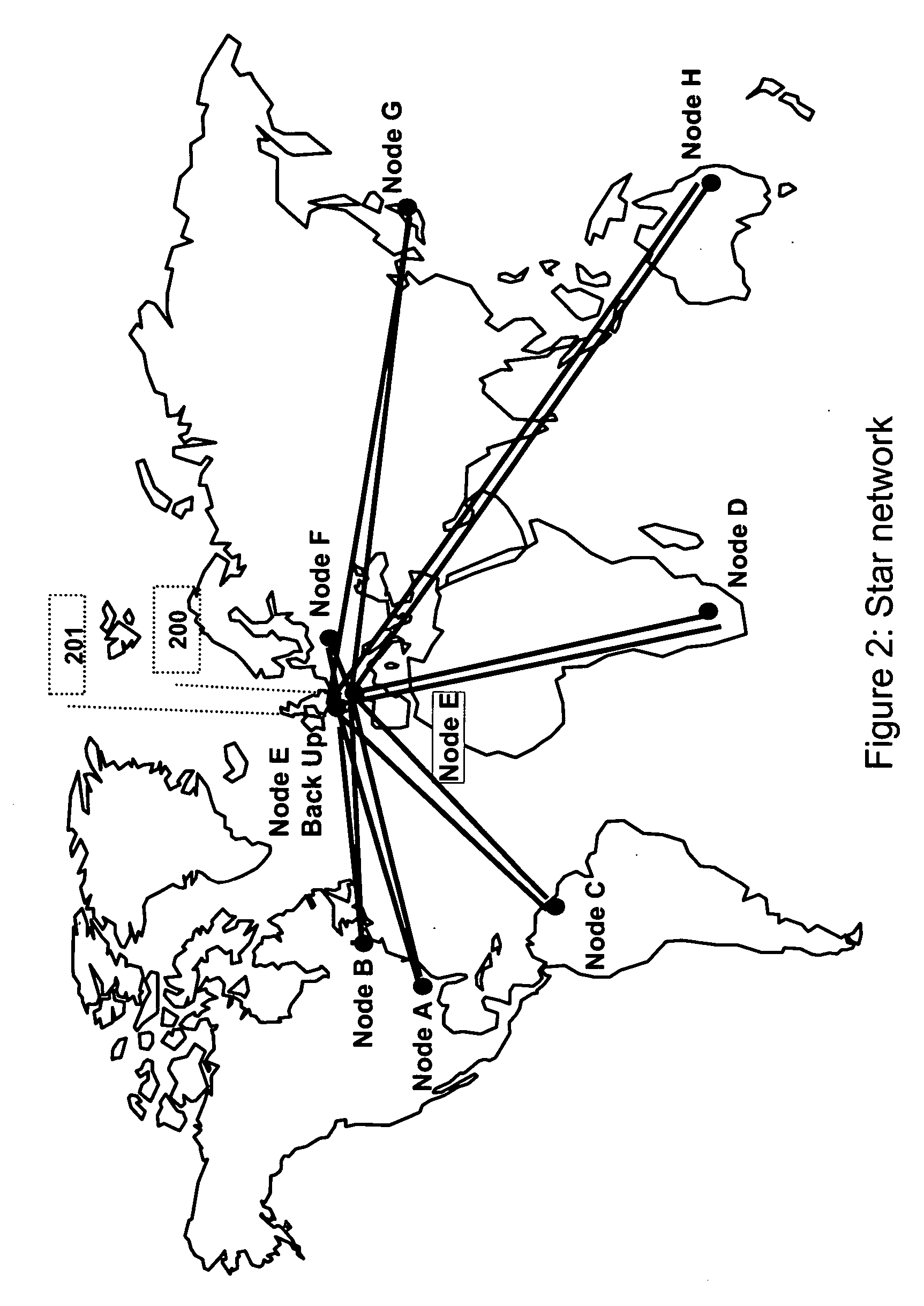
This configuration called “Star network” reduces the number of connections (N−1 sessions) but the main drawback is due to the fact that the central node is the weakest point of the network.

Method used


Image

  • System and method for optimizing the topology of a virtual ring based upon a TCP/IP network
  • System and method for optimizing the topology of a virtual ring based upon a TCP/IP network
  • System and method for optimizing the topology of a virtual ring based upon a TCP/IP network

Examples


Embodiment Construction

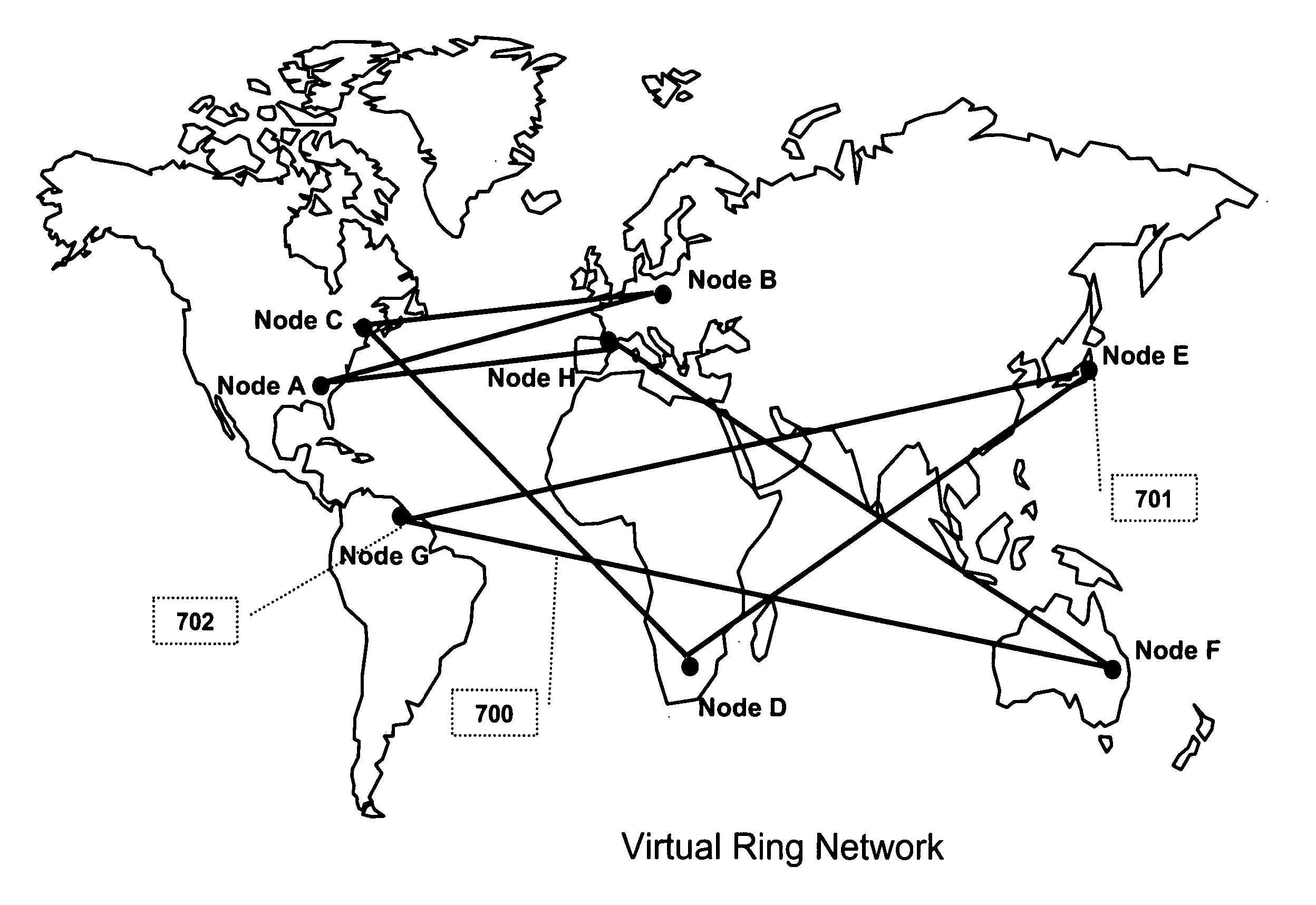
[0072] The present invention discloses a network topology based on a virtual ring. The N nodes of the network that need to communicate together, are logically / virtually connected according to a virtual ring, each node communicating with two and only two neighbour nodes: an upstream neighbour node and a downstream neighbour node. The present invention describes an insertion procedure to optimize the topology of this Virtual Ring and ensure a shortest path between adjacent neighbours.

[0073] Although the present invention applies to any types of nodes, this invention is particularly interesting when several nodes need to exchange a same piece of information between them.

[0074] Virtual Ring Network

[0075] Several Virtual Rings can be implemented on a same physical network, each Virtual Ring allowing a subset of nodes to communicate together. A same node can participate in several Virtual Rings at the same time. Each Virtual Ring is identified by a unique identifier (named Virtual Ring...


PUM


Abstract

In a network having nodes, N nodes are members of a virtual communications ring for multicast communication among the N nodes, each of the N nodes being associated with only an upstream and a downstream one of the other N nodes. One of the N nodes manages changes in ring membership, including requesting the others of the N nodes to participate in measuring distances to a N+1th, node responsive to receiving an insertion request message. The manager node inserts the N+1th node in the communications ring responsive to receiving replies, which includes inserting the N+1th node in a selected location between two selected ones of the N nodes, such that the N nodes and the N+1th node are enabled to multicast messages around the ring. Due to the selected location of the N+1th node, communication distances for muticasted messages tend to be shorter than such distances that would otherwise occur.

Description

FIELD OF THE INVENTION [0001] This application is a U.S. counterpart application of earlier filed application 05300797.7 / EP05300797, which was filed in the European Patent Office, Oct. 6, 2005. Applicants hereby claim the benefit of this earlier filed application under 35 U.S.C. 119. FIELD OF THE INVENTION [0002] The present invention relates to communication on digital networks, and more particularly to a system and a method for optimizing the topology of a virtual ring used to multicast datagrams in a TCP / IP (Transmission Control Protocol / Internet Protocol) environment. BACKGROUND OF THE INVENTION [0003] Topology of Networks [0004] In the present description, the term “Network” designates an ordinary network, based on the Internet Protocol (IP) technology. This network can be a Local Area Network (LAN), but also an Enterprise (private) Intranet or even the (public) Internet. The term “Node” designates the computer systems in the network routing the communications, such as routers,...

Claims


Application Information

Patent Timeline
Patent Type & Authority Applications(United States)
IPC IPC(8): H04L12/26H04L12/56
CPCH04L12/42H04L69/16H04L69/22H04L69/161H04L69/163
Inventor DENECHEAU, LIONELDISPENSA, JEAN-CLAUDEESTEVE, DENIS
Owner IBM CORP
Learn More