Process for tuning an EMI filter to reduce the amount of heat generated in implanted lead wires during medical procedures such as magnetic resonance imaging

Inactive Publication Date: 2007-04-12
GREATBATCH SIERRA INC
View PDF17 Cites 56 Cited by
  • Summary
  • Abstract
  • Description
  • Claims
  • Application Information

AI Technical Summary

Benefits of technology

[0014] The present invention resides in a process for tuning an EMI filter for an active implantable medical device (AIMD), wherein the EMI filter has a capacitor and an inductor/resistor element. The novel process of the present invention comprises the steps of: (1) evaluating input impedance of the AIMD; (2) configuring the physical relationship of the capacitor and the inductor/resistor element of the EMI filter based on the evaluated input impedance of the AIMD; (3) iteratively selecting component values for the capacitor and the inductor/resistor elements of the EMI filter; and (4) analyzing the impedance characteristics of the selected components through circuit simulation to assess (a) whether the impedance of the EMI filter has been raised suffi

Problems solved by technology

Compatibility of cardiac pacemakers, implantable defibrillators and other types of AIMDs with magnetic resonance imaging (MRI) and other types of hospital diagnostic equipment has become a major issue.
There have been reports of latent problems with cardiac pacemakers after an MRI procedure occurring many days later.
The lossy ferrite inductor or toroidal slab concept as described herein is not intended to provide protection against static magnetic fields such as those produced by magnetic resonance imaging.
These excessive currents can cause heating of the lead wire through high power (I2R) loss or heating in tissue due to excessive current flowing through tissue itself.
In those cases, the series inductance self resonates with the capacitor thereby rendering the capacitor ineffective as an EMI filter above the self-resonant frequency (the capacitor literally becomes inductive).
However, the presence of the EMI filtered feedthrough capacitor, by definition, reduces the input impedance of the implantable medical device.
However, this situation presents a dilemma when the AIMD patient is exposed to medical device procedures, such as MRI.
This can cause overheating

Method used


Image

  • Process for tuning an EMI filter to reduce the amount of heat generated in implanted lead wires during medical procedures such as magnetic resonance imaging
  • Process for tuning an EMI filter to reduce the amount of heat generated in implanted lead wires during medical procedures such as magnetic resonance imaging
  • Process for tuning an EMI filter to reduce the amount of heat generated in implanted lead wires during medical procedures such as magnetic resonance imaging

Examples


Embodiment Construction

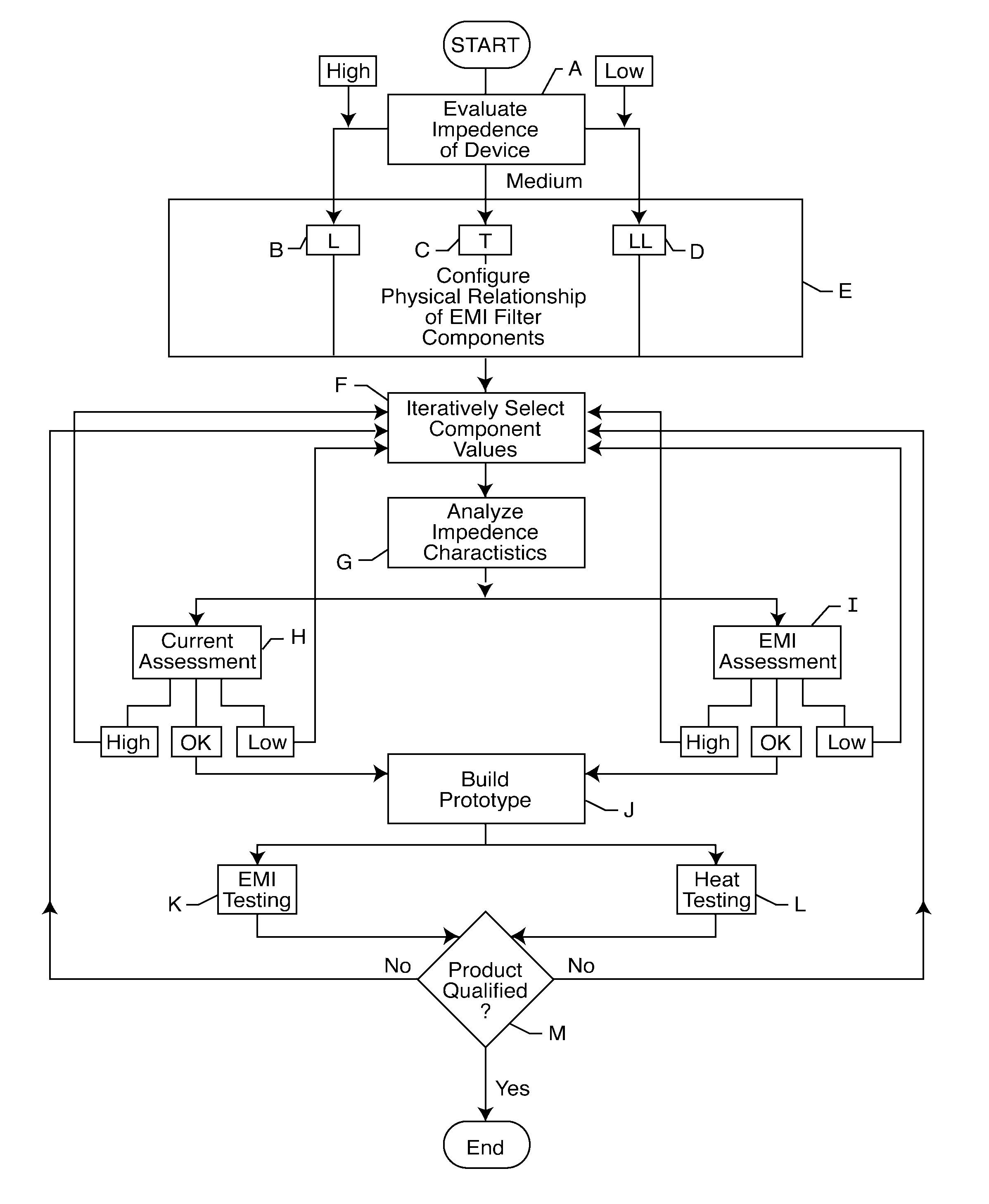
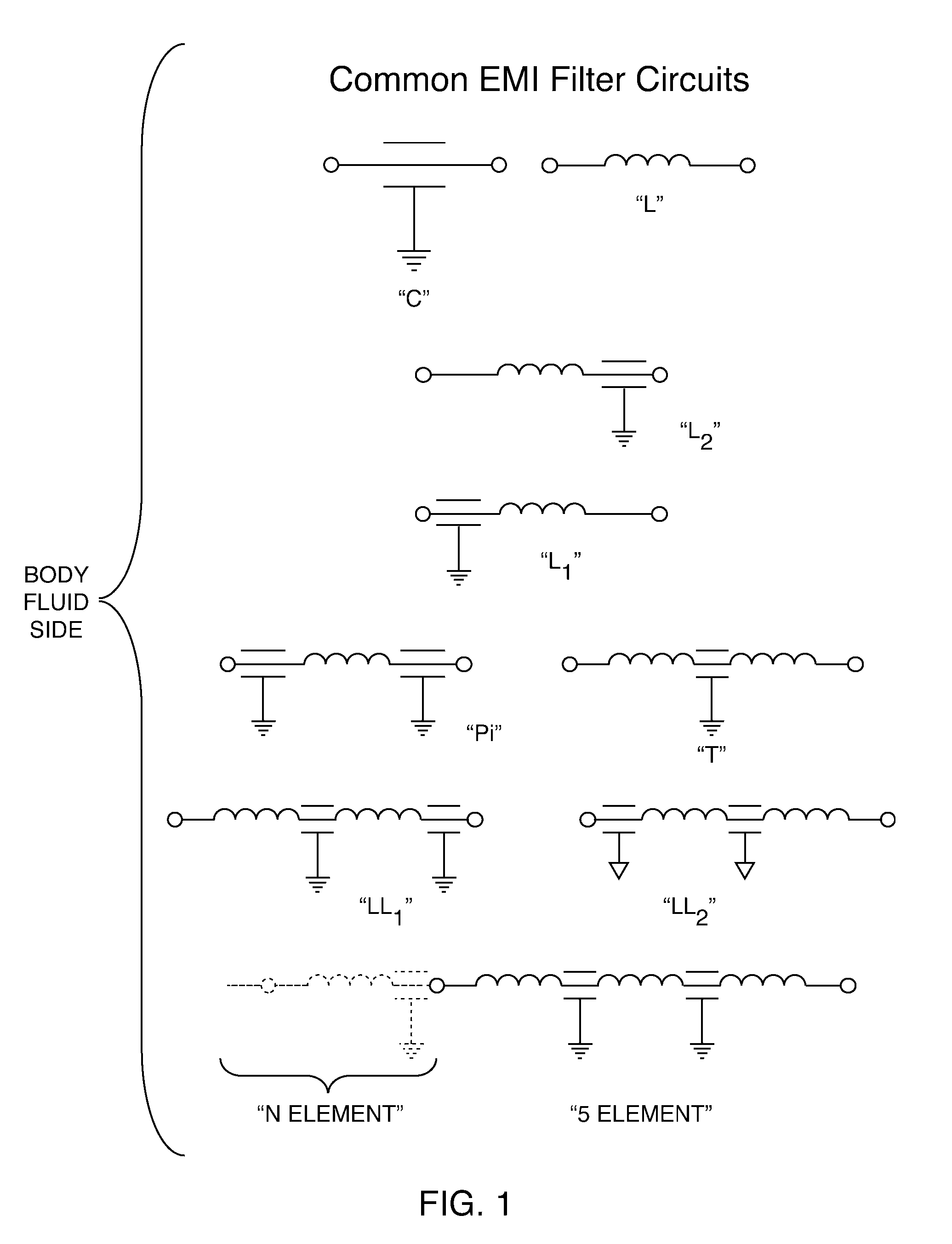
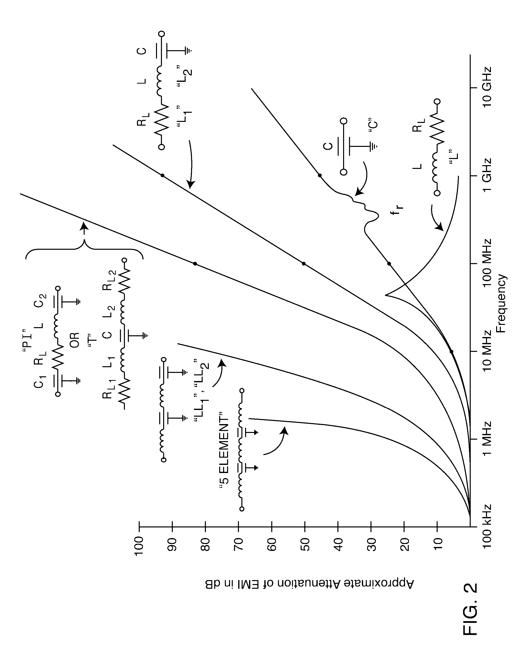
[0033] With reference to FIG. 2, the present invention requires a tuning or balancing of one or more feedthrough capacitors which are placed in series with one or more lossy (resistive) ferrite slab, inductor and / or resistive elements. The presence of the lossy ferrite slab and / or multiple turn inductor elements provides a series resistance and reactance. These series reactances tend to raise the AIMD input impedance. As previously described in the co-pending applications, the additional circuit elements also increase the attenuation slope of the EMI filter. This can be clearly seen in FIGS. 1 and 2. These figures are identical to FIGS. 20 and 21 of U.S. patent application Ser. No. 11 / 097,999, and similar to FIG. 53 of U.S. patent application Ser. No. 10 / 825,900, the contents of which applications are incorporated herein by reference.

[0034]FIG. 1 shows common EMI filter circuits such as C, L, PI, etc. It is only the C circuit that has been in common use in cardiac pacemakers to dat...


PUM


Abstract

In EMI filter assemblies incorporating one or more passive filter elements including feedthrough capacitors and lossy ferrite inductors, a process is provided for tuning the various components to reduce the amount of heat generated in implanted lead wires during medical procedures such as magnetic resonance imaging. The process includes selection and testing of individual components and an interative process involving tradeoffs and subsequent testing prior to finalization of the feedthrough design.

Description

BACKGROUND OF THE INVENTION [0001] This invention generally relates to EMI filter assemblies incorporating one or more passive filter elements including feedthrough capacitors and lossy ferrite inductors, or conventional inductors or the like. These EMI filter assemblies are typically used in active implantable medical devices (AIMDs), such as cardiac pacemakers, cardioverter defibrillators, neurostimulators and the like, for decoupling and shielding internal electronic components of the AIMD from undesirable electromagnetic interference (EMI) signals. [0002] Compatibility of cardiac pacemakers, implantable defibrillators and other types of AIMDs with magnetic resonance imaging (MRI) and other types of hospital diagnostic equipment has become a major issue. If one goes to the websites of the major cardiac pacemaker manufacturers in the United States, which include St. Jude Medical, Medtronic and Guidant, one will see that the use of MRI is generally contra-indicated with pacemakers ...

Claims


Application Information

Patent Timeline
IPC IPC(8): A61N1/00
CPCA61B5/055A61N1/056A61N1/08A61N1/375A61N1/3754A61B5/7203A61N1/37512
Inventor STEVENSON, ROBERT A.FRYSZ, CHRISTINE A.
Owner GREATBATCH SIERRA INC
Why Eureka
Try Eureka