Safety tank level gauging system

a safety tank and gauging technology, applied in the direction of liquid/fluent solid measurement, machines/engines, instruments, etc., can solve the problems of increasing the cost of the battery, increasing the difficulty of determining the amount of fluid being used, and increasing the difficulty of calculation, so as to prolong the battery life, save energy, and save costs.

Inactive Publication Date: 2007-04-19
BJ SERVICES CO
View PDF4 Cites 58 Cited by
  • Summary
  • Abstract
  • Description
  • Claims
  • Application Information

AI Technical Summary

Benefits of technology

[0016] In an alternative embodiment, the transducer may include means for both wirelessly transmitting and receiving data. Such means could include any wireless device, such as a radio transceiver for example, as would be recognized by one of ordinary skill in the art having the benefit of this disclosure. The unit could then direct such transducers to measure the fluid level in its respective tank. The unit may send directives to the transducers at regular intervals or directives could be sent upon manual instructions by an operator of the unit. In some embodiments the transducers could go into a standby mode between measurements to conserve energy.
[0017] One embodiment of the present disclosure overcome the issues addressed above by combining ultrasonic and wireless technology to automate the process of gauging the fluid level in a fracturing fluid tank. The system may include a level sender unit that a small, e.g. 1.5″ by 6″, portable battery power unit suspended in the tank over the fracturing fluid on a bracket. A clamp or magnetic mount easily attaches the bracket. The units sense the level of the tanks by an ultrasonic range finder. This information is sent via a radio link to a small portable handheld unit, which may be about the size of a calculator, that monitors all the tanks on a given job site. Multiple handheld units can all read the same information. The handheld unit also has a data output for interface to a computer system in the well treatment analyzer vehicle. The handheld nature of the device allows an operator to verify and / or calibrate the system while actually viewing the tanks if desired. The handheld unit would also display flow rate as a backup to the primary job flowmeters. Small inexpensive ultrasonic and radio transmitter modules are currently available which make it possible to construct this unit to be very small and rugged with an extended battery life, which may be several weeks up to several months, for a reasonable cost. This same embodiment could also be used to monitor the level in proppant bulk trucks and help reduce potential safety hazards in monitoring the proppant level.

Problems solved by technology

This can be rather difficult task as it is common for a work site to have between twenty to fifty tanks on site.
The relatively large number of tanks can make it difficult to determine the amount of fluid being used because the change in fluid level should be constantly monitored in each tank.
The tanks in a large group of tanks may be of various shapes and sizes making this calculation relatively difficult and time consuming.
Further, the large number of tanks makes it difficult to measure the fluid level simultaneously in each tank.
This method can be expensive, as it requires excessive time and labor to measure the liquid level of each tank.
Additionally, the overall data provided by this measuring system lacks accuracy because of the elapsed time between the measurements taken of the first tank and of the last tank.
The difficulties associated with the strapping tank method are exasperated when making such measurements during inclement weather.
In inclement weather, this procedure can prove unsafe.
Fracturing fluid tanks are generally large rectangular shaped vessels, but some fracturing fluid tanks may be cylinders oriented longitudinally along the ground, which are more difficult and dangerous to work on top of because of the curved top surface.
Additionally, the worker may have to take these manual measurements during conditions that are windy, extremely hot, or severely cold.
Each of these inclement conditions increases the likelihood of an accident occurring while measuring each and every tank at the work site.
The size of these tanks can cause serious injury if the worker were to slip or fall off.
Another potential problem of the current method is the accuracy of each individual measurement.
Occasional errors in measurements will likely result due to the manual nature of the measurement.
The propensity to make errors may be increased due to the strenuous task of measuring the fluid levels of large numbers of tanks at a work site or due to severe weather conditions.
However, the method described above may not allow for an instantaneous calculation of flow rate of the system due to the amount of time required to measure and record the fluid level of each and every tank.
Further, inaccurate measurements, which will likely be present in manual measurements, will also decreases the accuracy in the flow rate calculations.
Additionally, the flow rate out of the tanks may not remain constant.
Often this fluid may be hazardous or present harmful results to humans if exposed over an extended length of time.
Monitoring the mixture level in proppant bulk trucks also presents some similar problems.
This can be a less-than-safe task for the worker as the proppant could shift or the worker could possibly fall into the hopper.
Also the proppant in the hopper of a truck may not be level, but instead be at an angle making it more difficult to a worker to determine the amount of proppant remaining in the hopper.
However, the frequent movement of the tanks may limit the use of a system of sensors wired to a central processor due to the time required to disconnect and reconnect the wires to configure the system, in addition to the time required to refill and hydraulically connect each tank.

Method used


Image

  • Safety tank level gauging system
  • Safety tank level gauging system

Examples


Embodiment Construction

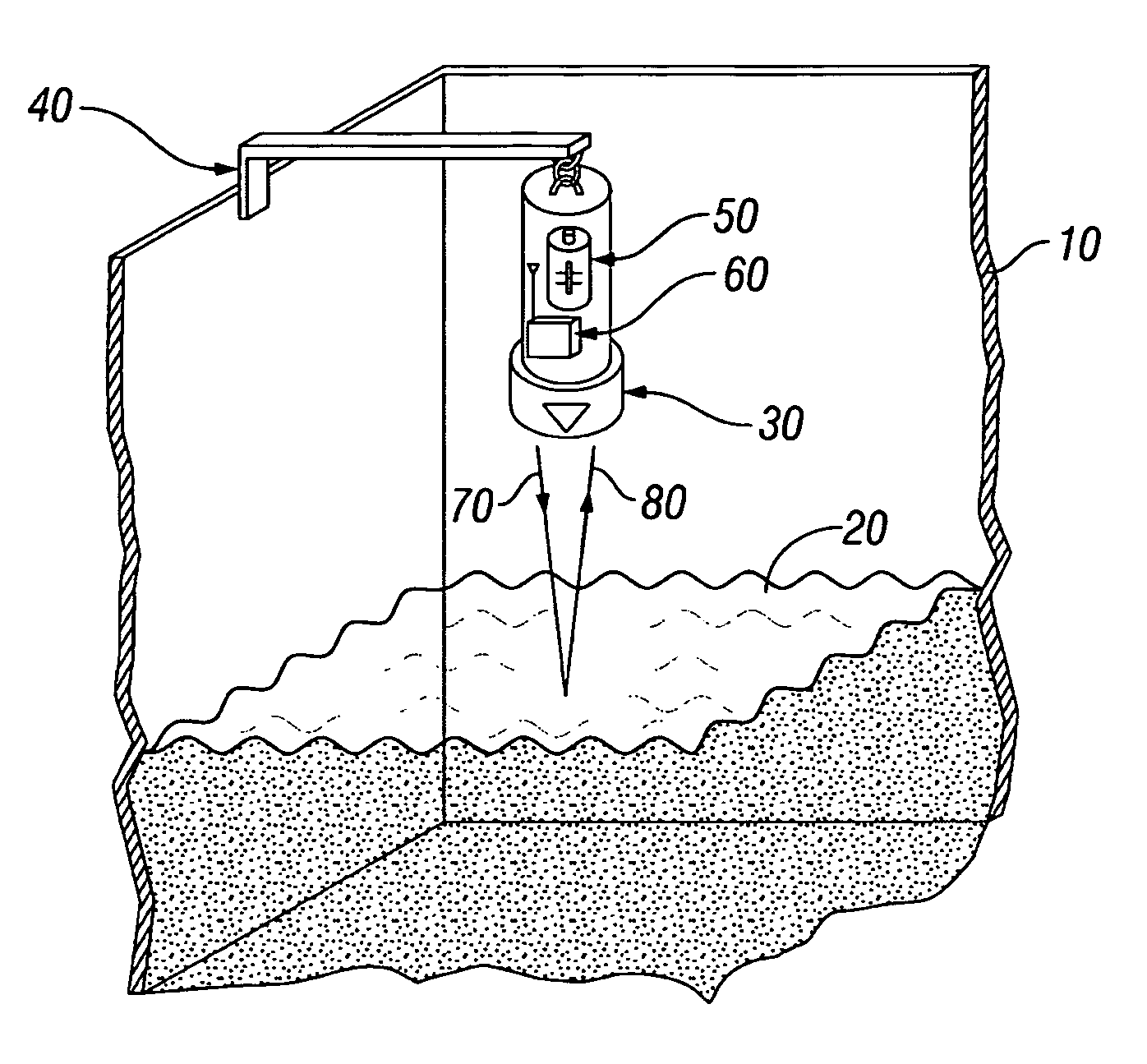
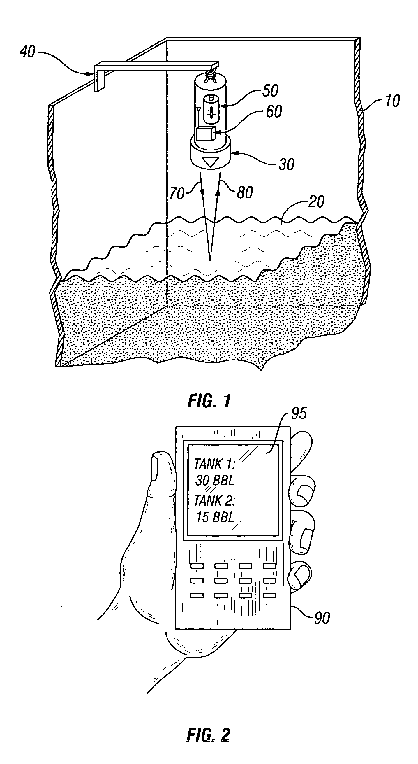
[0028] Illustrative embodiments of the invention are described below as they might be employed in the use of designing an apparatus or system to measure the fluid level of a tank or a network of tanks. In the interest of clarity, not all features of an actual implementation are described in this specification. It will of course be appreciated that in the development of any such actual embodiment, numerous implementation-specific decisions must be made to achieve the developers' specific goals, such as compliance with system-related and business-related constraints, which will vary from one implementation to another. Moreover, it will be appreciated that such a development effort might be complex and time-consuming, but would nevertheless be a routine undertaking for those of ordinary skill in the art having the benefit of this disclosure.

[0029] Further aspects and advantages of the various embodiments of the invention will become apparent from consideration of the following descrip...


PUM


Abstract

An apparatus and method is disclosed to automate the measurement of the fluid levels of individual tanks used at the work site of an oil well. An ultrasonic transducer may be removably attached to each tank at the site. The fluid level of each tank may be determined from the time elapsed from the transmission of an ultrasonic signal from the transducer and when a signal reflected from the fluid is received at the transducer. The transducer may wirelessly transmit a signal representative of the fluid level to a receiving unit. The receiving unit may be able to instantaneously determine the overall fluid flow rate from the tanks based on the fluid levels when compared to previous fluid levels. The transducers may take fluid level measurements at regular intervals or may make measurements only when directed by the receiving unit.

Description

BACKGROUND OF THE INVENTION [0001] 1. Field of the Invention [0002] The present invention relates generally to a gauging apparatus and method for measuring the level of fluid in tanks in the oilfield service environment. [0003] 2. Description of the Related Art [0004] In the oilfield service industry, a work site may contain numerous tanks for holding liquid or other material. One such type of tank is for holding fracturing fluid used to stimulate oil and gas wells. It is important to monitor the fluid levels of each tank in an attempt to monitor the amount of fracturing fluid being used, as well as to know when replacement tanks or the re-filling of tanks is needed. This can be rather difficult task as it is common for a work site to have between twenty to fifty tanks on site. The relatively large number of tanks can make it difficult to determine the amount of fluid being used because the change in fluid level should be constantly monitored in each tank. The level of fluid in each...

Claims


Application Information

Patent Timeline
Patent Type & Authority Applications(United States)
IPC IPC(8): G01F23/28G08B21/00G01F23/296
CPCG01F1/007G01F23/0069G01F23/2962G01F23/2968H04Q9/00G01F23/802
Inventor CARLSON, BRADLEY T.HUGHES, RONNIE
Owner BJ SERVICES CO
Why Eureka
Try Eureka